Manufacturing and forming method for rotor punching sheet of servo motor

A technology of rotor punching and servo motor, which is applied in the field of servo motor rotor punching equipment, can solve the problems of wasting man-hours, affecting the quality of servo motor rotor punching, missing or over-grinding, etc., and achieves the effect of convenient material return work

Pending Publication Date: 2022-06-03
蔡义强
View PDF1 Cites 2 Cited by
  • Summary
  • Abstract
  • Description
  • Claims
  • Application Information

AI Technical Summary

Problems solved by technology

The present invention can solve the following problems in the use process of existing grinding machines: a: most of the servo motor rotor punches that need to be ground in the market are special-shaped parts, not standard parts, and it is very easy to use conventional grinding equipment for grinding. The phenomenon of missed grinding or over-grinding occurs, which seriously affects the quality of servo motor rotor punching and wastes costs; b: when grinding in the current market, a single servo motor rotor punching is sequentially polished, which seriously wastes man-hours. When grinding a single servo motor rotor punch, the grinding degree of each servo motor rotor punch will not be consistent, which will easily lead to the scrapping of the servo motor rotor punch
[0004] However, the purpose of the servo motor rotor punching production device is not convenient for oblique symmetrical production, which is not conducive to the symmetrical collaborative production function, which will cause certain inconvenience. Production works, needs to be improved

Method used


Image

  • Manufacturing and forming method for rotor punching sheet of servo motor
  • Manufacturing and forming method for rotor punching sheet of servo motor
  • Manufacturing and forming method for rotor punching sheet of servo motor

Examples


Embodiment Construction

[0038] The technical solutions in the embodiments of the present invention will be clearly and completely described below with reference to the accompanying drawings in the embodiments of the present invention. Obviously, the described embodiments are only a part of the embodiments of the present invention, rather than all the embodiments. Based on the embodiments of the present invention, all other embodiments obtained by those of ordinary skill in the art without creative efforts shall fall within the protection scope of the present invention.

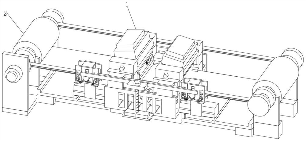
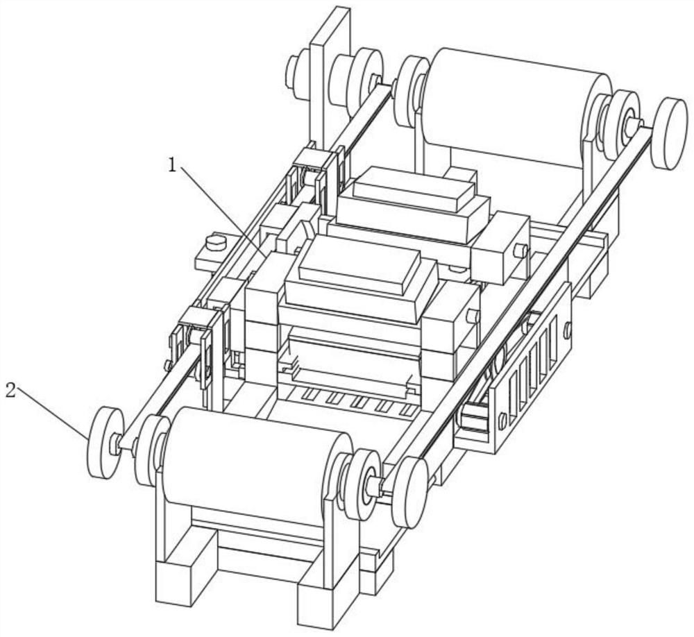
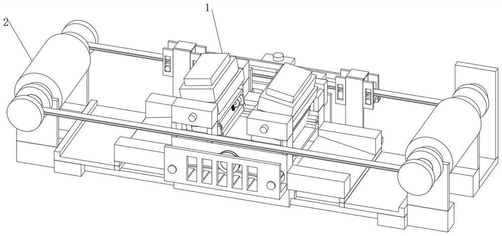
[0039] see Figure 1-10 , The present invention provides a technical solution: a method for manufacturing and forming a servo motor rotor punching piece, comprising a punching production structure 1, a side end position of the punching production structure 1 is limitedly connected with an adjusting feeding structure 2, and the punching production structure 1, Adjust the combination setting of the feeding structure 2, realize the over...


PUM


Abstract

The invention discloses a servo motor rotor punching sheet manufacturing and forming method which comprises a stamping production structure, the side end position of the stamping production structure is connected with an adjusting feeding structure in a limiting mode, and the stamping production structure comprises a first stamping part, a transmission inclined guide part and a second stamping part. The conveying inclined guide part is arranged at the bottom of the inner end of the stamping production structure, one side of the upper end of the conveying inclined guide part is fixedly connected with the first stamping part, and the other side of the upper end of the conveying inclined guide part is fixedly connected with the second stamping part. According to the manufacturing and forming method for the rotor punching sheet of the servo motor, the purpose of manufacturing and forming the rotor punching sheet of the servo motor at the inner end is achieved through the arrangement of a pressing production structure.

Description

technical field [0001] The invention relates to the technical field of servo motor rotor punching equipment, in particular to a manufacturing and forming method for servo motor rotor punching. Background technique [0002] The servo motor rotor punching sheet can be used for the installation and production of the servo motor, realize the efficient assembly and connection work of the servo motor, facilitate the integrated installation and cooperation, realize the purpose of conduction driving, and realize the efficient driving function. [0003] According to Chinese Patent No. CN201910898385.0, the present invention relates to a servo motor rotor punching and forming device, which includes a mounting frame, a grinding kit and a rotating mechanism, and is characterized in that: a grinding kit and a rotating mechanism are sequentially arranged inside the mounting frame from top to bottom. mechanism. The invention can solve the following problems a in the use process of the exi...

Claims


Application Information

Patent Timeline
Patent Type & Authority Applications(China)
IPC IPC(8): H02K15/02B65G47/74
CPCH02K15/02B65G47/74Y02P70/10
Inventor 蔡义强
Owner 蔡义强
Why Eureka
Try Eureka