
Fine shearing device for steels

A precision shearing and steel technology, applied in the direction of shearing device, nibbling cutting device, shearing machine equipment, etc., can solve the problems of low operating safety factor, low material utilization rate, high processing cost, etc., and achieve the goal of operation Safe and reliable, shorten processing cycle, simple and reasonable structure

Active Publication Date: 2011-09-07
SHANDONG YUJIE BEARING MFG CO LTD
View PDF6 Cites 2 Cited by
  • Summary
  • Abstract
  • Description
  • Claims
  • Application Information

AI Technical Summary

Problems solved by technology

[0002] At present, the cutting process of steel generally adopts lathe cutting. During processing, the steel is first fixed on the lathe, and then the cutting process is carried out by manual measurement and manual adjustment of the feeding length. High, the operation safety factor is not high, and the material utilization rate is low, resulting in high processing costs

Method used


Image

  • Fine shearing device for steels
  • Fine shearing device for steels
  • Fine shearing device for steels

Examples


Embodiment Construction

[0014] In order to clearly illustrate the technical features of this solution, the present invention will be described in detail below through specific implementation modes and in conjunction with the accompanying drawings.

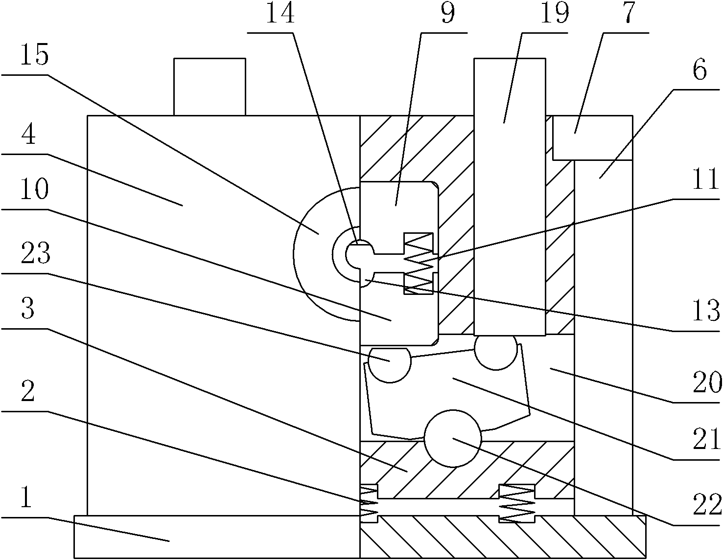
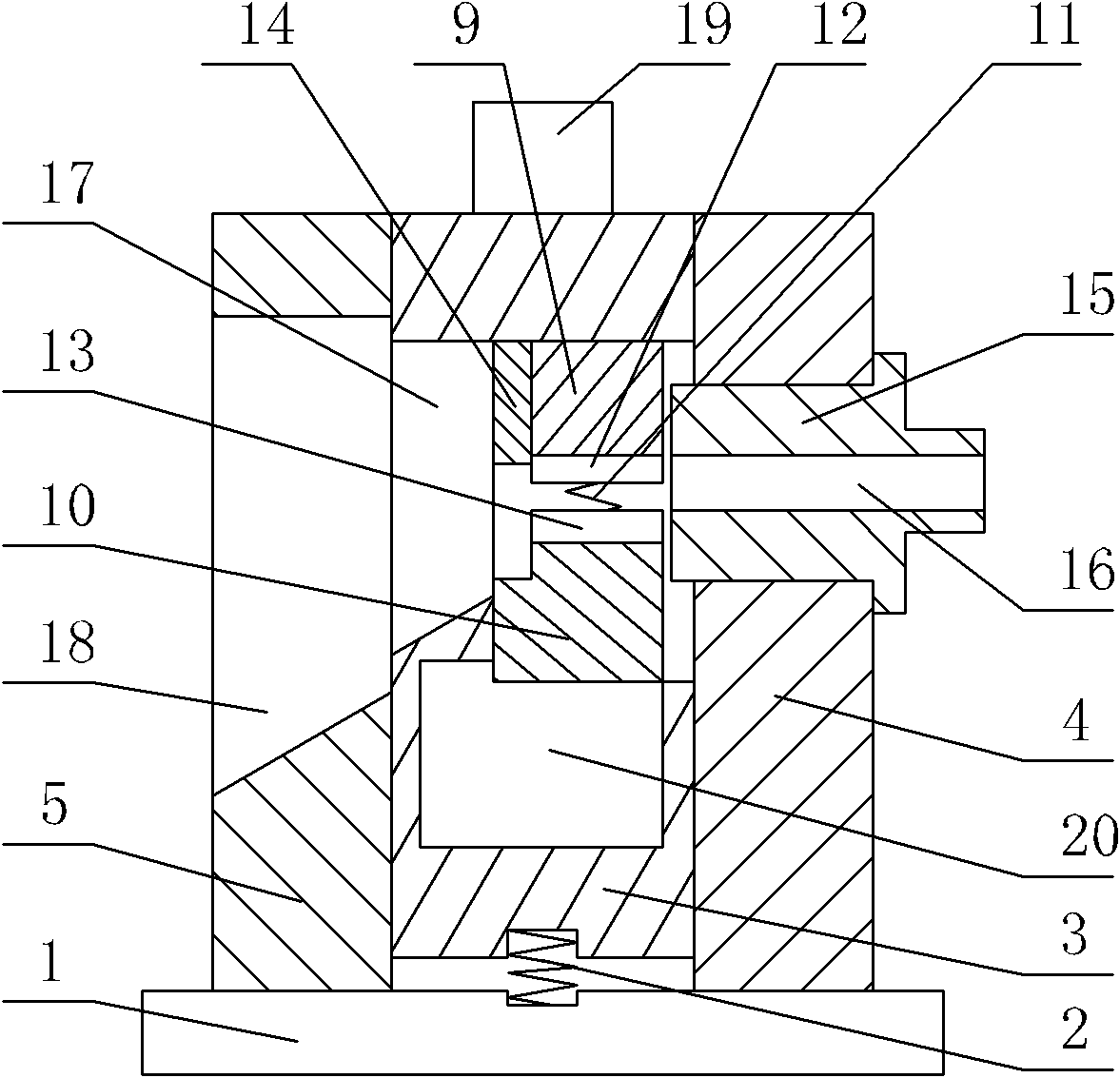
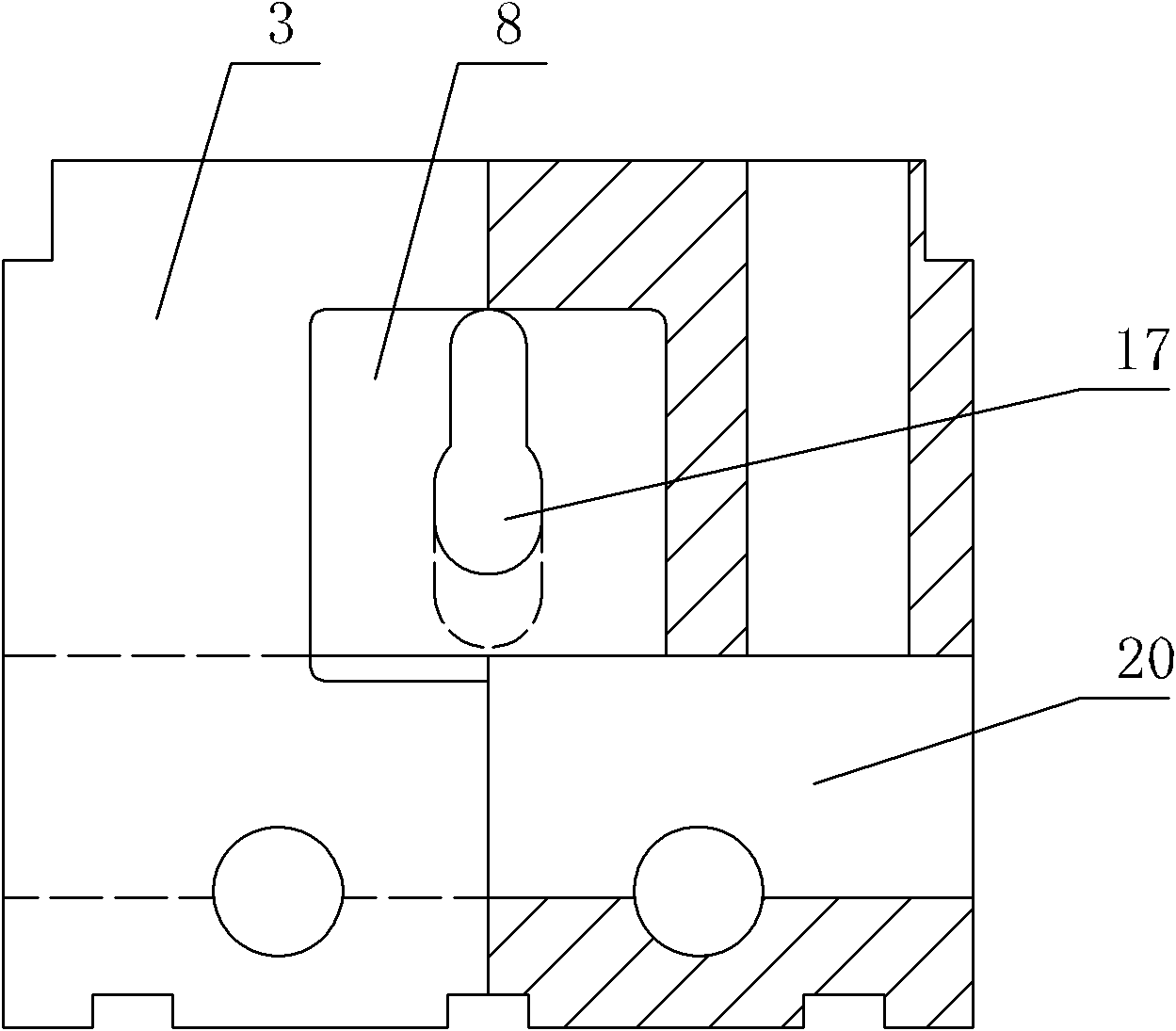
[0015] Such as Figure 1~4 As shown, the present invention comprises a base 1, a slide block 3 is fixedly connected to the base 1 top by a first spring 2, and a front fender 4, a rear fender 5 and Both side baffles 6 are respectively provided with a limit block 7 to block the slider 3 at the top of the two side baffles 6; an upper movable mold 9 and a lower movable mold 10 are arranged in the middle square groove 8 on the front side of the slider 3 , the upper movable mold 9 and the lower movable mold 10 are connected by a second spring 11, and the lower surface of the upper movable mold 9 and the upper surface of the lower movable mold 10 are respectively provided with an upper trough 12 and a lower trough 13, which are opposite to each other. The rear ...


PUM


Abstract

The invention discloses a fine shearing device for steels, which is characterized in that a base is fixedly connected with a slide block by a first spring, a front baffle plate, a rear baffle plate and two side baffle plates are arranged around the slide block, and the tops of the two side plates are respectively provided with a limit block; an upper moving die and a lower moving die which are connected by a second spring are arranged in a square groove arranged at the front side of the slide block, and the opposite surfaces of the upper and lower moving dies are respectively provided with an upper material chute and a lower material chute; the rear part of the upper moving die is fixedly connected with a material blocking plate of which the lower end slightly blocks the rear end of the upper material chute; the position of a feed hole of a fixed die fixedly arranged on the front baffle plate is opposite to the position of the upper material chute, a blanking outlet corresponding to the upper and lower material chutes is arranged at the rear side of the slide block, and a discharge outlet corresponding to the blanking outlet is arranged on the rear baffle plate; and the two parts of the slide block at the two sides of the upper and lower moving dies are respectively internally provided with a compression bar which is connected with a lower pressing device, the upper ends of the compression bars extend out of the slide block; two movable transmission blocks are symmetrically arranged in an elongated slot arranged in the slide block below the lower moving die, and the two ends of the upper part of each transmission block are symmetrically provided with two ejector rods, wherein the ejector rod at the inner end abuts against the lower moving die, and the ejector rod at the outer end abuts against the lower end of the compression bar. The fine shearing device for steels disclosed by the invention is easy, safe and reliable to use and has high efficiency.

Description

Technical field: [0001] The invention relates to a steel cutting and processing equipment, in particular to a steel precision shearing device. Background technique: [0002] At present, the cutting process of steel generally adopts lathe cutting. During processing, the steel is first fixed on the lathe, and then the cutting process is carried out by manual measurement and manual adjustment of the feeding length. This operation is time-consuming and laborious. Not only is the work efficiency poor High, the operation safety factor is not high, and the material utilization rate is low, resulting in high processing costs. Invention content: [0003] The invention provides a steel precision shearing device, which is simple in structure, easy to use, safe and reliable in operation, saves time and effort, can quickly and accurately cut off the required length of material rod, has high work efficiency and high material utilization rate, and solves the problem of existing problems...

Claims


Application Information

Patent Timeline
Patent Type & Authority Applications(China)
IPC IPC(8): B23D27/00
Inventor 蔡梅贵崔建阁陈德生任艳强蔡圣阳
Owner SHANDONG YUJIE BEARING MFG CO LTD
Learn More