Luneberg lens

A Lumberg lens, triangle technology, used in antennas, instruments, optics, etc., can solve problems such as deformation and lens performance degradation

Pending Publication Date: 2022-06-03
NAT UNIV OF SINGAPORE
View PDF0 Cites 1 Cited by
  • Summary
  • Abstract
  • Description
  • Claims
  • Application Information

AI Technical Summary

Problems solved by technology

However, these proposed structures become fragile after the additive manufacturing process is completed, especially after the removal of the supports used in the additive manufacturing process, which can easily lead to deformation and degradation of the performance of the lens.

Method used


Image

  • Luneberg lens
  • Luneberg lens
  • Luneberg lens

Examples


Embodiment Construction

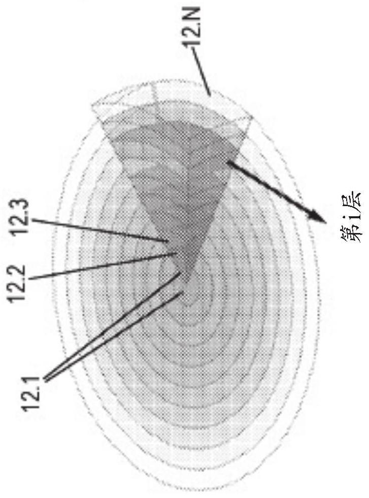
[0050] Embodiments of the present disclosure generally relate to a Luneburg lens comprising a plurality of concentrically arranged layers, each layer being formed by a plurality of triangular regions. Lumberg lenses can be used as part of high gain lens antennas with multi-beam radiation targets for millimeter wave wireless communication applications. Antennas according to some embodiments have wide operating bandwidths, wide scanning angles, and flexible polarization matching capabilities.

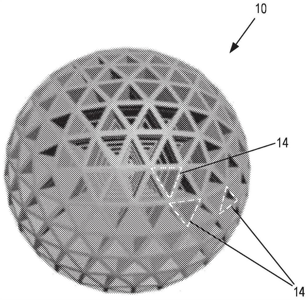
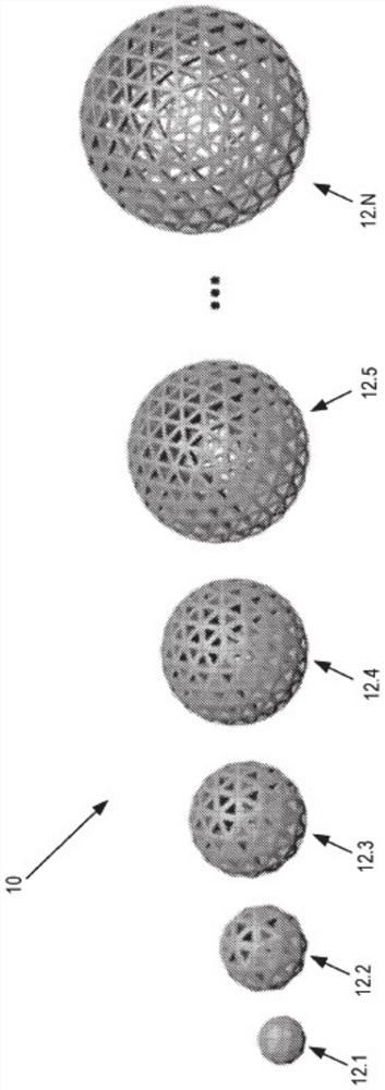
[0051] will now refer to Figure 1 to Figure 4 Embodiments of Lumberg lenses are described. Lumberg lens 10 includes a plurality of concentrically arranged layers that are figure 2 are marked as 12.1 to 12.N. figure 2 A series of such layers is shown from left (innermost) to right (outermost).

[0052]Each layer 12.1 to 12.N is formed by a plurality of triangular regions 14. The triangular regions 14 form a tile of approximately spherical surfaces. For example, the plurality of tr...


PUM


Abstract

The Luneberg lens includes a plurality of centrally arranged spherically symmetric layers, each layer formed of a plurality of triangular regions. The plurality of triangular regions of each layer form a short-range linear polyhedron, such as a regular icosahedron. Each triangular region includes one or more apertures, and each aperture may be triangular.

Description

technical field [0001] The present disclosure relates to Luneburg lenses, and to antenna devices including Luneburg lenses. Background technique [0002] Luneburg lens (LL) antennas have several known advantages, such as being broadband in nature and having high gain and multi-beam capability, which are especially important in applications such as 5G communication systems. Since electromagnetic waves suffer from high atmospheric propagation loss and blocking in the high frequency bands where 5G devices operate, point-to-point wireless applications (i.e. mobile backhaul transmission networks) require antennas with high gain performance and wide scanning range to achieve high spatial cover. [0003] Compared to other multi-beam antennas such as phased array antennas, Lumberg lens antennas are immune to scanning losses and do not require complex and expensive feed networks, making them ideal for mmWave communications. [0004] The radial permittivity variation of a Lumberg le...

Claims


Application Information

Patent Timeline
Patent Type & Authority Applications(China)
IPC IPC(8): H01Q15/08H01Q19/06G02B6/124
CPCH01Q15/08H01Q19/06
Inventor 郭永新王聪吴杰
Owner NAT UNIV OF SINGAPORE
Why Eureka
Try Eureka