Constant current function detection device of LED power supply

A technology for LED power supply and function detection, which is applied in power supply testing and the use of semiconductor lamps. It can solve problems such as LED power supply damage, LED power supply bursting, and reduced device practicability, so as to reduce production costs, strengthen protection effects, and ensure stability. sexual effect

Inactive Publication Date: 2022-06-07
深圳市创诺新电子科技有限公司
View PDF12 Cites 0 Cited by
  • Summary
  • Abstract
  • Description
  • Claims
  • Application Information

AI Technical Summary

Problems solved by technology

[0003] The inventor found that at least the following problems in the prior art have not been resolved: 1. When the existing detection device detects the LED power supply, the detection probe will have a downward detection impact on the LED power supply during the detection process, which may It will cause damage to the LED power supply, thereby affecting the quality of the LED power supply and increasing the production cost of the LED power supply; 2. During the detection process of the existing detection device, the device will light the LED power supply. It will cause damage to the eyesight of the staff, and at the same time, during the inspection, the LED power supply may burst due to voltage instability, which poses a safety hazard, and the existing detection device cannot automatically recycle the unqualified LED power supply, which reduces the practicability of the device; Therefore, we propose a constant current function detection device for LED power supplies

Method used


Image

  • Constant current function detection device of LED power supply
  • Constant current function detection device of LED power supply
  • Constant current function detection device of LED power supply

Examples


Embodiment Construction

[0031] In order to make the technical means, creative features, achievement goals and effects realized by the present invention easy to understand, the present invention will be further described below with reference to the specific embodiments.

[0032]In the description of the present invention, it should be noted that the terms "upper", "lower", "inner", "outer", "front end", "rear end", "two ends", "one end" and "the other end" The orientation or positional relationship indicated by etc. is based on the orientation or positional relationship shown in the accompanying drawings, which is only for the convenience of describing the present invention and simplifying the description, rather than indicating or implying that the indicated device or element must have a specific orientation, a specific orientation, and a specific orientation. The orientation configuration and operation are therefore not to be construed as limitations of the present invention. Furthermore, the terms ...


PUM


Abstract

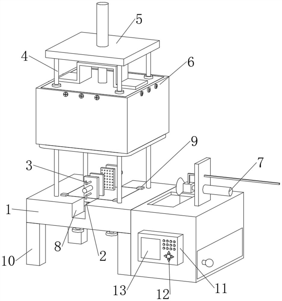
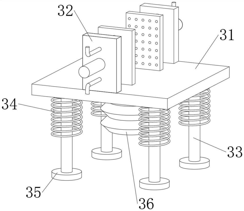
A constant current function detection device for an LED power supply disclosed by the present invention comprises a detection table, the middle part of the upper end of the detection table is provided with a buffer groove, four corners of the lower groove wall of the buffer groove are jointly inserted and movably connected with a buffer mechanism, and the middle part of the front groove wall and the middle part of the rear groove wall of the buffer groove are both provided with movable grooves. Supporting columns are fixedly connected to the four corners of the upper end of the detection table, a top plate is jointly and fixedly connected between the upper ends of the four supporting columns, a detection mechanism is movably connected to the middle of the upper end of the top plate in a penetrating mode, and supporting legs are fixedly connected to the four corners of the lower end of the detection table. And a recovery mechanism is fixedly connected between the right ends of the two supporting legs on the right side and the right end of the detection table. According to the constant current function detection device of the LED power supply, the whole detection device is convenient to detect the constant current function of the LED power supply, the protection effect is good, a buffer effect can be achieved, inferior-quality products can be automatically recycled, and the constant current function detection device is suitable for wide application.

Description

technical field [0001] The invention relates to the technical field of LED power supply detection, in particular to a constant current function detection device of an LED power supply. Background technique [0002] LED power supply is a kind of power supply. It is a device that provides power to electronic equipment, and it is also a power supply. It is used to convert alternating current into direct current through transformers and rectifiers. The LED power supply must have a constant current function, because once the operating current of the LED exceeds The rated current will quickly reduce the service life of the LED, and the LED will be quickly aged and damaged. Therefore, the constant current function of the LED power supply is very important. Therefore, sometimes a detection device is needed to perform constant current detection on the LED power supply. can be used; [0003] The inventor found that at least the following problems have not been solved in the prior art...

Claims


Application Information

Patent Timeline
Patent Type & Authority Applications(China)
IPC IPC(8): G01R31/40
CPCG01R31/40Y02B20/30
Inventor 吴清吴尚华
Owner 深圳市创诺新电子科技有限公司
Why Eureka
Try Eureka