U-shaped steel bar storage device and storage and hoisting method
A technology for storage devices and steel bars, applied in tool storage devices, manufacturing tools, etc., can solve the problems of cumbersome management of U-shaped steel bar products, large storage area, and large demand for engineering labor, so as to achieve enhanced efficiency and reliability Operability, reduce floor space, and ensure the effect of maximizing utilization
- Summary
- Abstract
- Description
- Claims
- Application Information
AI Technical Summary
Problems solved by technology
Method used
Image
Examples
Embodiment 1
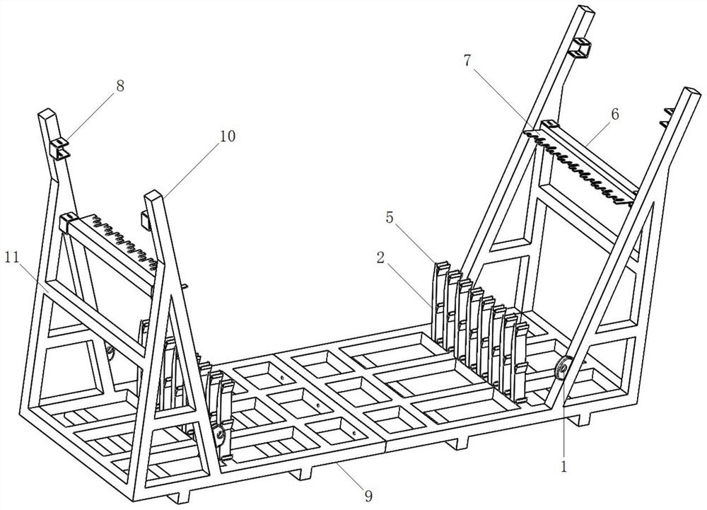
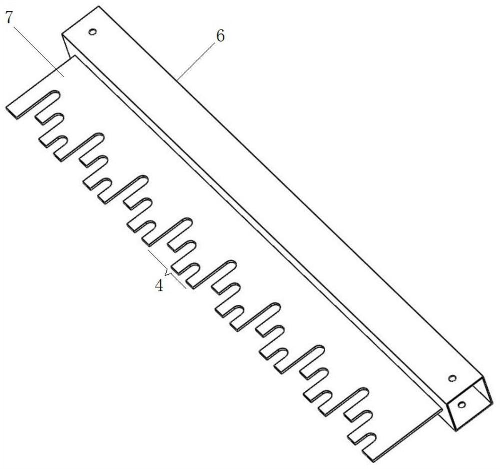
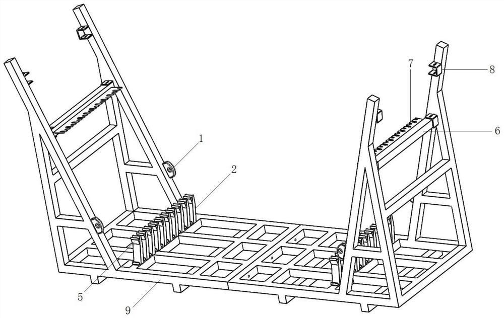
[0035] This embodiment provides a U-shaped steel bar storage device, including a left frame, a middle frame, a right frame, a bottom support and a side support beam; The supporting beam mounting frame 10; the side bottom frames 9 of the left frame and the right frame are located on the lateral sides of the middle frame, and are detachably connected with the middle frame; the supporting beam mounting frame 10 is provided with a lifting ring 1; the side bottom frames 9 and / or Bottom supports are fixed on the middle frame, each group of bottom supports includes y bottom support columns 2 arranged vertically, and z bottom card slots 3 for supporting the bottom edge of U-shaped steel bars are vertically arranged on the bottom support columns 2; There are two sets of upper and lower clamping grooves, the lateral support beams are installed in the upper clamping groove or the lower clamping groove, and the opposite sides of the two lateral support beams are provided with lateral clamp...
Embodiment 2
[0041] This embodiment provides a U-shaped steel bar storage device for a standard section of a single-line beam, which includes a left-marked frame and a marked-right frame; The supporting beam mounting frame 10 and the connecting beam 11 connecting the supporting beam mounting frame 10 are provided with a set of bottom supports on the side chassis 9, and three bottom support sheets 5 are provided on the sides of the bottom support column 2 to form three bottom card slots 3, Every three lateral slots 4 on the support beam is a group, and the slot depths of the three lateral slots 4 in the same group increase or decrease sequentially and are the same as the three bottom slots 3 on the same bottom support column 2. One-to-one correspondence (the depth of the three lateral card slots 4 increases in turn, the height of the three bottom card slots 3 increases in turn, or the slot depth of the three lateral card slots 4 increases in turn corresponding to the three bottom card slots ...
Embodiment 3
[0050] This embodiment provides a U-shaped steel bar storage device for a single-line beam with variable end section, including a left-changing frame and a right-changing frame, which are similar in structure to the left and right-bid frames in Embodiment 1; the left- and right-changing frames both include side bottoms The frame 9, the support beam mounting frame 10 fixed on the front and rear sides of the side chassis 9, and the connecting beam 11 connecting the support beam mounting frame 10, the side chassis 9 is provided with a set of bottom supports, and the side of the bottom support column 2 is provided with two The support piece 5 at the bottom of the block forms two bottom slots 3, each two lateral slots 4 on the lateral support beam is a group, and the slot depths of the two lateral slots 4 in the same group increase or decrease in turn and Corresponding one-to-one with the two bottom slots 3 on the same bottom support column 2, the side chassis 9 that changes to the ...
PUM
 Abstract
Description
Claims
Application Information
 - R&D
- Intellectual Property
- Life Sciences
- Materials
- Tech Scout
- Unparalleled Data Quality
- Higher Quality Content
- 60% Fewer Hallucinations
Browse by: Latest US Patents, China's latest patents, Technical Efficacy Thesaurus, Application Domain, Technology Topic, Popular Technical Reports.
© 2025 PatSnap. All rights reserved.Legal|Privacy policy|Modern Slavery Act Transparency Statement|Sitemap|About US| Contact US: help@patsnap.com


