Waveguide end array antenna for reducing grating lobes and cross polarization

An array antenna and waveguide technology, which is suitable for antennas on movable objects, antenna arrays and antennas that are powered separately, can solve problems such as error detection

Pending Publication Date: 2022-06-21
APTIV TECH LTD
View PDF0 Cites 0 Cited by
  • Summary
  • Abstract
  • Description
  • Claims
  • Application Information

AI Technical Summary

Problems solved by technology

However, if the radiation pattern includes multiple grating lobes, the car may falsely detect that the pedestrian is standing next to the car when in fact the pedestrian is standing in front of the car

Method used


Image

  • Waveguide end array antenna for reducing grating lobes and cross polarization
  • Waveguide end array antenna for reducing grating lobes and cross polarization
  • Waveguide end array antenna for reducing grating lobes and cross polarization

Examples


example 1

[0043] EXAMPLE 13: The apparatus of any preceding example, wherein the waveguide end array antenna is further configured to: reduce the amount of EM energy when the at least a portion of the EM energy is dissipated to the outside of the dielectric core. cross-polarization of the radiation of the EM energy, wherein the EM energy further comprises a polarization of the EM energy; the polarization is configured to enable the EM energy to oscillate in a direction; all of the radiation The cross-polarization includes: at least two directions of the EM energy from at least two radiating troughs; and the at least two directions are different.

example 2

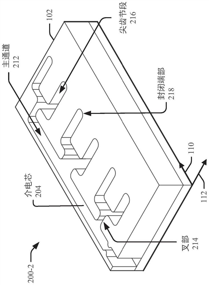
[0044] Example 14: The device of any preceding example, wherein the size of the main channel increases as the number of the at least one prong increases.

example 3

[0045] Example 15: The device of the preceding examples, wherein the dielectric core comprises air.


PUM


Abstract

This document describes techniques, apparatuses, and systems relating to waveguide end array antennas for reduced grating lobes and cross polarization. For a brief purpose, it is referred to as a waveguide, electromagnetic energy is directed from a waveguide input to one or more radiating slots using a core made of a dielectric material. The dielectric core includes a main channel and one or more prongs. Each fork connects the primary channel to one or more tines segments, and each tines segment terminates in a closed end and a radiating slot. The radiating slots are separated from each other by a distance such that at least a portion of the electromagnetic energy is dissipated in phase through the radiating slots. The dielectric core of the waveguide reduces grating lobes and cross polarization associated with electromagnetic energy. The automobile may rely on the waveguide to detect an object with increased accuracy.

Description

Related Application Cross Reference [0001] This application claims the benefit of U.S. Provisional Application No. 63 / 169,104, filed March 31, 2021, and U.S. Provisional Application No. 63 / 127,842, filed December 18, 2020, under 35 U.S.C. 119(e), which The disclosure of the provisional application is hereby incorporated by reference in its entirety. Background technique [0002] Some devices, such as radars, transmit or receive electromagnetic (EM) energy via one or more antennas to detect objects. These antennas can emit EM energy as radiation and can be characterized in terms of a radiation pattern. The effective radiation pattern may include a maximum (eg, a grating lobe) of radiation used to determine the position of the object. The radiation pattern can be improved using waveguides to direct EM energy to the antenna. However, some waveguides can cause the antenna to produce multiple grating lobes in the radiation pattern, partly due to cross-polarization of EM energy...

Claims


Application Information

Patent Timeline
IPC IPC(8): H01Q1/36H01Q21/00
CPCH01Q21/00H01Q1/36H01Q1/3233H01Q21/0043H01Q13/18H01Q21/08H01Q1/32H01Q13/10H01Q21/0068
Inventor 李明鉴
Owner APTIV TECH LTD
Why Eureka
Try Eureka