Dual band, dual pole, 90 degree azimuth BW, variable downtilt antenna

a dual-pole, variable technology, applied in the field of antennas, can solve the problem that the optimal value of downtilt is not always predictable, and achieve the effect of uniform phase shift and downtilt adjustmen

Inactive Publication Date: 2007-02-06
ALLEN TELECOM LLC
View PDF11 Cites 43 Cited by
  • Summary
  • Abstract
  • Description
  • Claims
  • Application Information

AI Technical Summary

Benefits of technology

[0007]The present invention achieves technical advantages as a dual band, dual pole, variable downtilt antenna having a microstrip feed network formed upon a PC board, and having horizontal dielectric elements slidable upon the microstrip feed network to achieve uniform phase shift and downtilt. Advantageously, the dielectric members are slidingly disposed upon serpentine portions of the microstrip feeding respective dipole elements to achieve uniform downtilt adjustment while using a microstrip architecture. Advantageously, this dual band, dual pole antenna achieves a complete 90 degree azimuth beamwidth which heretofore has never been provided in one device, especially with a device having variable downtilt.
[0008]In one preferred embodiment, the antenna includes a first set of dipole elements forming a first band such as a PCS band antenna, and a second set of dipole elements forming a second band such as a cellular band antenna. The second band is collectively configured as two linear arrays of antenna elements arranged parallel to a center line of dipole elements forming the PCS band antenna, the elements of one array being 90° with respect to the other array of antennas. Advantageously, the dipole elements of each band are fed by a microstrip network formed upon a conventional PC board. The microstrip feed network of each band has serpentine portions with a dielectric material slideable thereover to achieve the necessary phase shifting of the beam pattern formed by each band of the antenna. Advantageously, a linear downtilt of up to 10 degrees is obtainable for the cellular band and up to 8 degrees for the PCS band, with a horizontal 90 degree azimuth beamwidth for each band in an overall package having a width of only 13 inches. The serpentine portions of the microstrip provide the necessary length of the fed while reducing the area needed on the PC board, and cooperate with the dielectric materials slideable thereover.

Problems solved by technology

However, the optimum value of downtilt is not always predictable prior to actual installation and testing.

Method used


Image

  • Dual band, dual pole, 90 degree azimuth BW, variable downtilt antenna
  • Dual band, dual pole, 90 degree azimuth BW, variable downtilt antenna
  • Dual band, dual pole, 90 degree azimuth BW, variable downtilt antenna

Examples


Embodiment Construction

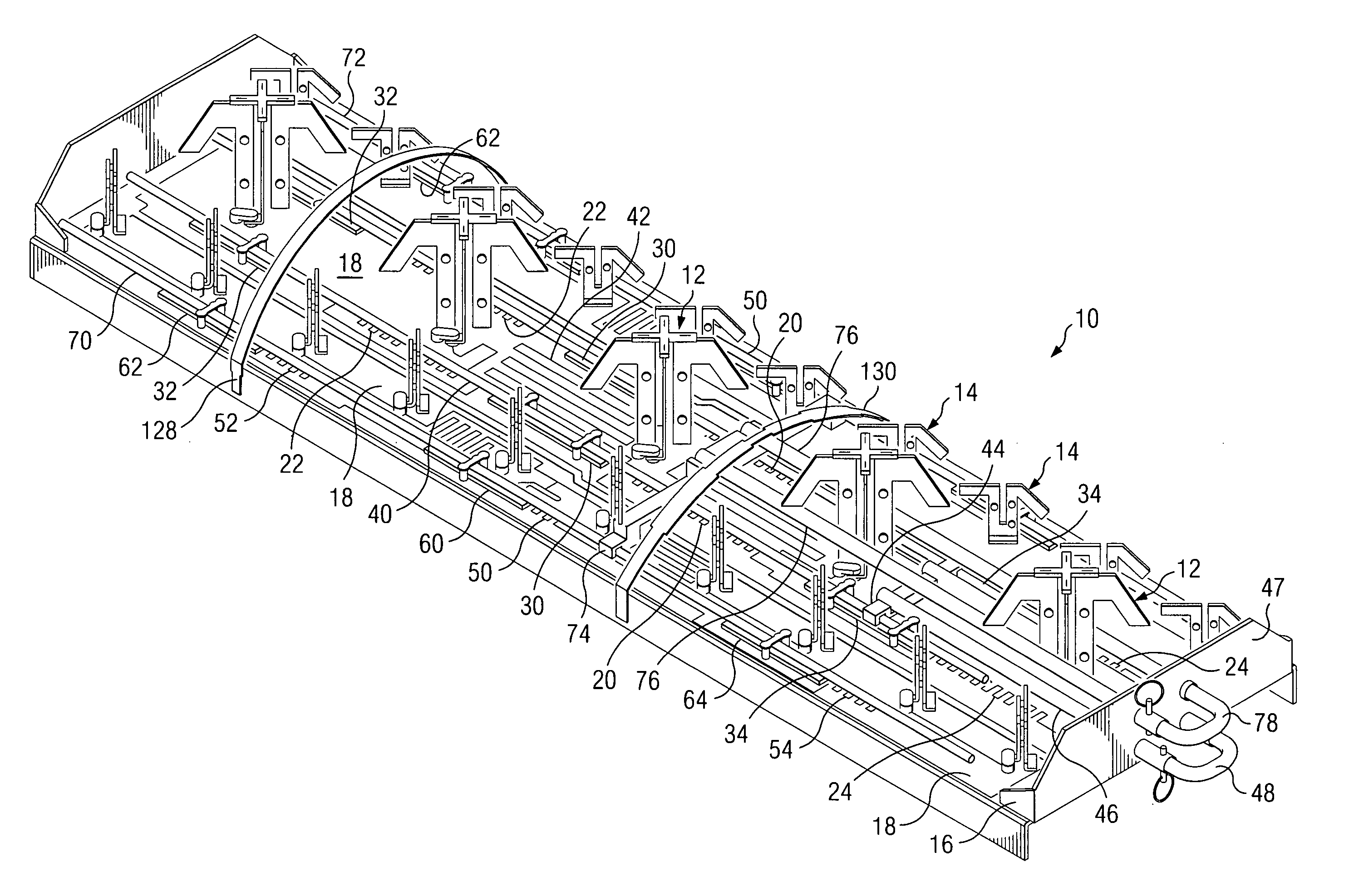
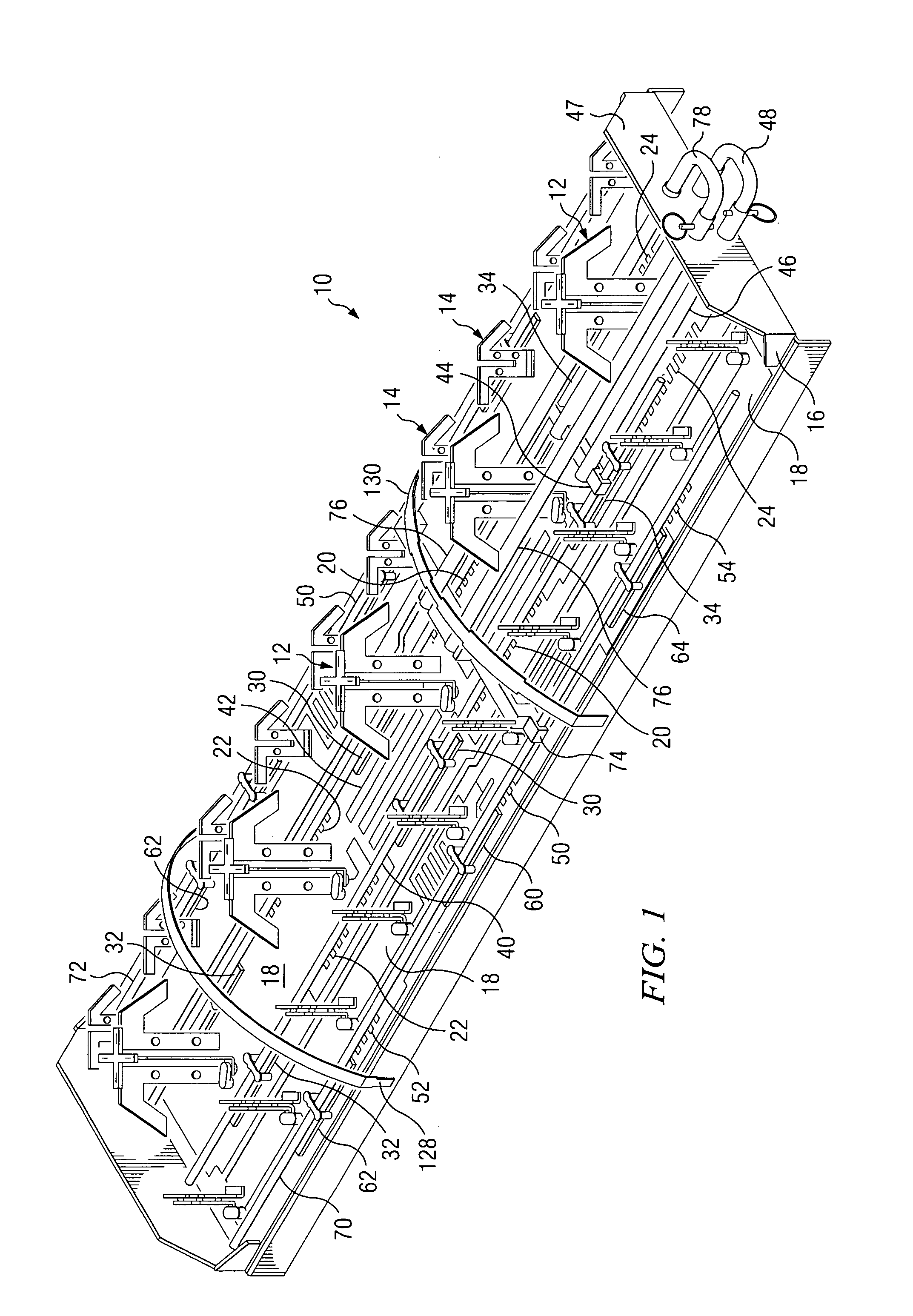
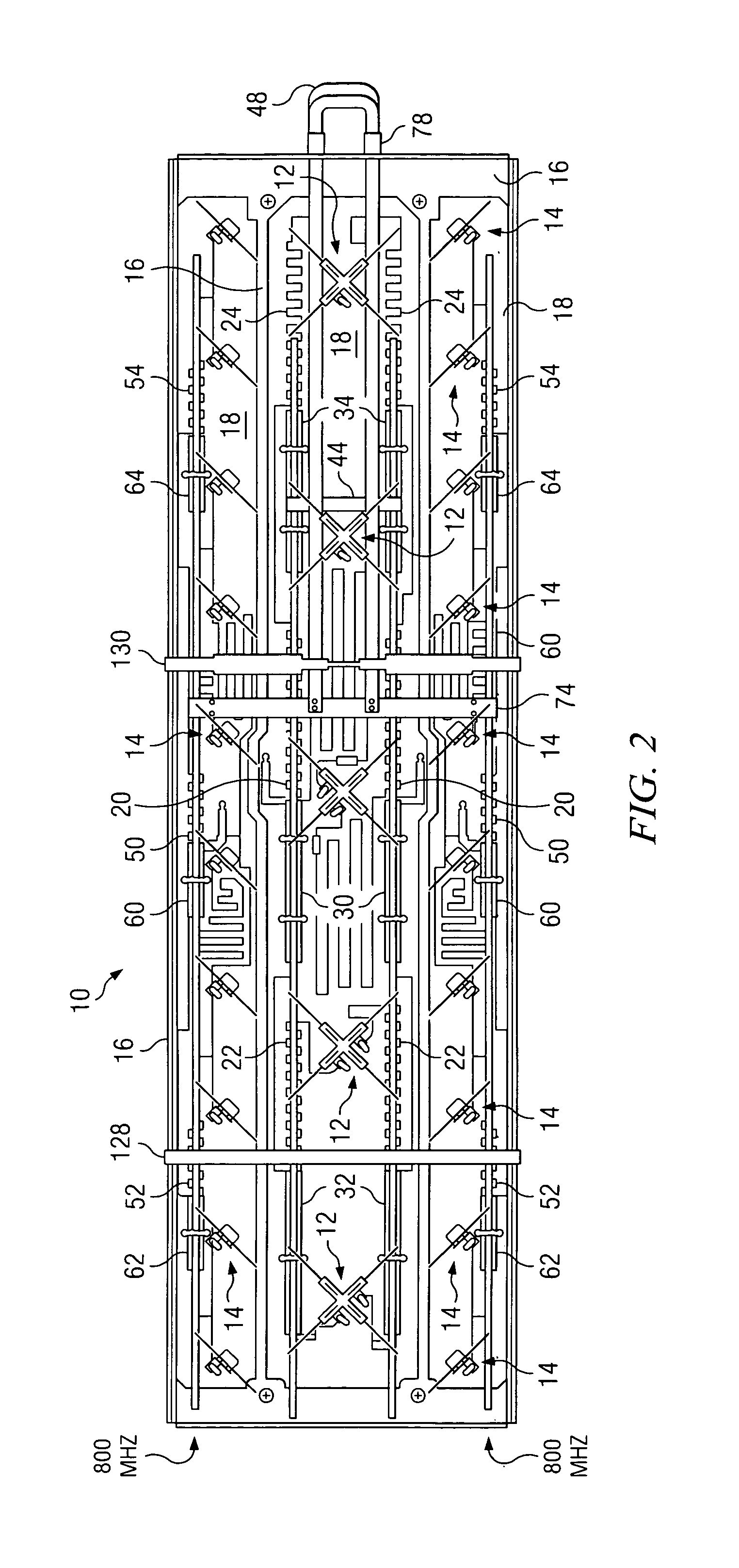
[0028]Referring now to FIG. 1, there is generally shown at 10 a dual band, dual pole, 90 degree horizontal azimuth beamwidth, variable downtilt antenna according to the preferred embodiment of the present invention. Antenna 10 is seen to include a first linear array of dipole elements 12 forming a cellular band antenna, and two linear arrays of antenna elements 14, one linear array arranged each side of the first linear array 12 and together forming dipole elements forming a PCS band antenna. For purposes of clarity, the antenna elements 14 along the nearside of the antenna have been omitted in this FIG. 1 to depict the various features of the antenna 10, including the microstrip feed system feeding each of the respective antenna arrays and formed upon respective PC boards having a backplane thereunder.

[0029]Advantageously, a first microstrip feed network has a pair of first serpentine portions 20 feeding the center dipole element 12. Each first serpentine portion 20 feeds a pair of...


PUM


Abstract

A dual band, dual pole, variable downtilt, 90 degree azimuth beamwidth antenna (10). The antenna includes dipole elements (12, 14) forming both a PCS band and a cellular band antenna. The PCS band antenna has two sections disposed each side of the cellular band antenna, the elements of each being positioned 90° with respect to the other. A microstrip feed network formed upon a common PC board (18) feeds the respective dipole elements, and has serpentine portions with a corresponding dielectric member slideable thereover to establish the phase of the associated dipole antennas and achieve a linear downtilt of the respective antenna array. A slide rod adjustment assembly (100) provides unitary movement of the dielectric members between two different slide rods. These dielectric members are secured with adhesive to the respective slide rods to achieve good dielectric control and no use of hardware. The radiating dipole elements are capacitively coupled to each microstrip, and are also capacitively associated reflector element. One arm of the reflector element is offset at least 45 degrees with respect to the other arm to improve cross polarization.

Description

PRIORITY CLAIM[0001]This application is a Continuation-in-Part of U.S. patent application Ser. No. 10 / 085,756 filed Feb. 28, 2002 entitled “Antenna Array Having Sliding Dielectric Phase Shifters”, now issued as U. S. Pat. No. 6,621,465.FIELD OF THE INVENTION[0002]The present invention is generally related to antennas, and more particularly, to mobile communication antennas including dual band, dual pole, variable downtilt antennas usable in PCS (1900 HZ) and cellular (800 MHz) wireless communication networks.BACKGROUND OF THE INVENTION[0003]Wireless mobile communication networks continue to be deployed and improved upon given the increased traffic demands on the networks, the expanded coverage areas for service and the new systems being deployed. Cellular type communication systems derive their name in that a plurality of antenna systems, each serving a sector or area commonly referred to as a cell, are implemented to effect coverage for a larger service area. The collective cells m...

Claims


Application Information

Patent Timeline
Patent Type & Authority Patents(United States)
IPC IPC(8): H01Q21/10H01Q1/24H01Q3/26H01Q3/30H01Q3/32H01Q3/36H01Q9/28H01Q21/24
CPCH01Q1/246H01Q3/26H01Q3/30H01Q21/24H01Q3/36H01Q9/285H01Q3/32
Inventor TEILLET, ANTHONYBONCZYK, MICHAEL F.TIMOFEEV, IGORLE, KEVINCAO, T. HUY
Owner ALLEN TELECOM LLC
Why Eureka
Try Eureka