Vehicle radar system

A radar system and vehicle technology, applied in the field of vehicle radar systems, can solve problems such as narrowing the observation distance range, narrowing the frequency band of the radar device, and shortening the observation time.

Pending Publication Date: 2022-06-21
DENSO CORP
View PDF2 Cites 0 Cited by
  • Summary
  • Abstract
  • Description
  • Claims
  • Application Information

AI Technical Summary

Problems solved by technology

However, as a result of detailed studies by the inventors, when three or more radar devices are mounted on a vehicle and time-division transmission is performed, the observation time allocated to each radar device becomes shorter and the observation distance range becomes narrower.
In addition, as a result of detailed studies by the inventors, when three or more radar devices are mounted on a vehicle and frequency-divided transmission is performed, the frequency band allocated to each radar device becomes narrow and the range resolution decreases.

Method used


Image

  • Vehicle radar system
  • Vehicle radar system
  • Vehicle radar system

Examples


no. 1 approach

[0017]

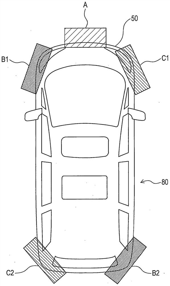
[0018] First, refer to figure 1 The configuration of the vehicle radar system 80 according to the present embodiment will be described. The vehicle radar system 80 includes a first radar device A, a second radar device B1, a third radar device C1, a fourth radar device B2, and a fifth radar device C2.

[0019] The first radar device A is a forward radar, and the second radar device B1, the third radar device C1, the fourth radar device B2, and the fifth radar device C2 are peripheral radars.

[0020] The first radar device A is mounted on the front center of the vehicle 50 (for example, the center of the front bumper). The detection area of ​​the first radar device A is a front center area of ​​the vehicle 50 .

[0021] The second radar device B1 is mounted on the left front side of the vehicle 50 (for example, at the left end of the front bumper). The detection area of ​​the second radar device B1 is a front left area of ​​the vehicle 50 . The third radar devic...

no. 2 approach

[0045]

[0046] The basic configuration of the second embodiment is the same as that of the first embodiment, so the description of the common configuration is omitted, and the difference is mainly described. In addition, the same reference numerals as in the first embodiment denote the same configuration, and the previous description is referred to.

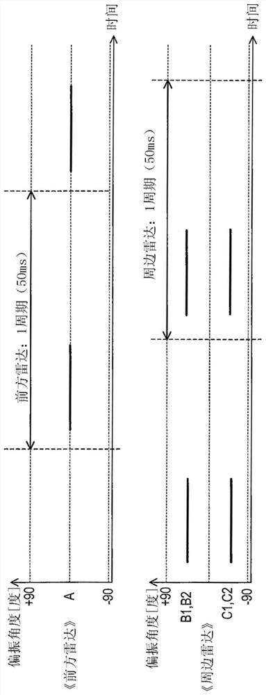
[0047] In the above-described first embodiment, the first to fifth radar devices A, B1, B2, C1, and C2 use a common transmission frequency and use different transmission times and transmission polarizations. On the other hand, in the second embodiment, the first to fifth radar devices A, B1, B2, C1, and C2 use a common transmission time and use different transmission frequencies and transmission polarizations, which is different from the first to fifth radar devices A, B1, B2, C1, and C2. One embodiment is different.

[0048] Specifically, as Figure 4 As shown, the first radar apparatus A transmits a first radar wave having...

no. 3 approach

[0054]

[0055] The basic configuration of the third embodiment is the same as that of the first embodiment, so the description of the common configuration is omitted, and the difference is mainly described. In addition, the same reference numerals as in the first embodiment denote the same configuration, and the previous description is referred to.

[0056] In the above-described first embodiment, the first to fifth radar devices A, B1, B2, C1, and C2 use a common transmission frequency and use different transmission times and transmission polarizations. On the other hand, in the third embodiment, the first to fifth radar devices A, B1, B2, C1, and C2 use a common transmission polarization and use different transmission times and transmission frequencies, which is different from the third embodiment. One embodiment is different.

[0057] In the present embodiment, the first to fifth radar devices A, B1, B2, C1, and C2 transmit two kinds of radar waves, respectively, the fa...


PUM


Abstract

A vehicle radar system according to one aspect of the present disclosure is provided with a first radar device (A), a second radar device (B1), and a third radar device (C1). The first radar device (A) transmits a first radar wave, the transmission time or transmission frequency of which is different from the transmission time or transmission frequency of the second radar wave transmitted by the second radar device (B1) and the third radar wave transmitted by the third radar device (C1). The second radar device (B1) transmits a second radar wave, the transmission polarization or transmission beam direction of which is different from the transmission polarization or transmission beam direction of the third radar wave transmitted by the third radar device.

Description

[0001] CROSS-REFERENCE TO RELATED APPLICATIONS [0002] The present international application claims the priority of Japanese Patent Application No. 2019-202344 filed in the Japan Patent Office on Nov. 7, 2019, and the entire contents of Japanese Patent Application No. 2019-202344 are incorporated herein by reference. technical field [0003] The present disclosure relates to a vehicle radar system including three or more radar devices. Background technique [0004] The sensor system described in the following Patent Document 1 includes a plurality of radio wave sensors installed at an intersection. A plurality of radio wave sensors perform time-division transmission or frequency-division transmission to suppress generation of radio wave interference between the radio wave sensors. In time-division transmission, a plurality of radio wave sensors transmit radio waves in mutually different periods. In addition, in frequency division transmission, a plurality of radio wave se...

Claims


Application Information

Patent Timeline
Patent Type & Authority Applications(China)
IPC IPC(8): G01S13/87G01S13/34G01S13/931
CPCG01S13/931G01S2013/93271G01S2013/93272G01S2013/93274G01S7/0231G01S13/343G01S7/0235G01S7/0232G01S13/341G01S13/87G01S2013/0236
Inventor 长谷川裕
Owner DENSO CORP
Why Eureka
Try Eureka