Laser measuring device for house measurement

A technology of laser measurement and housing, which is applied in the direction of measuring devices, optical devices, instruments, etc., can solve problems such as insufficient stability, decreased measurement accuracy, and easy shaking, and achieve the effect of improving practicability, improving accuracy, and not being easy to shake

Pending Publication Date: 2022-06-28
岳丹
View PDF0 Cites 0 Cited by
  • Summary
  • Abstract
  • Description
  • Claims
  • Application Information

AI Technical Summary

Problems solved by technology

[0003] 1. The existing laser measurement device used for house measurement is not stable enough when the device is placed on the ground, and it is easy to shake;
[0004] 2. The existing laser measuring device for house measurement cannot change the position of the measuring device, resulting in a decrease in measurement accuracy, and the device does not have the function of self-adjusting lifting

Method used


Image

  • Laser measuring device for house measurement
  • Laser measuring device for house measurement
  • Laser measuring device for house measurement

Examples


Embodiment 1

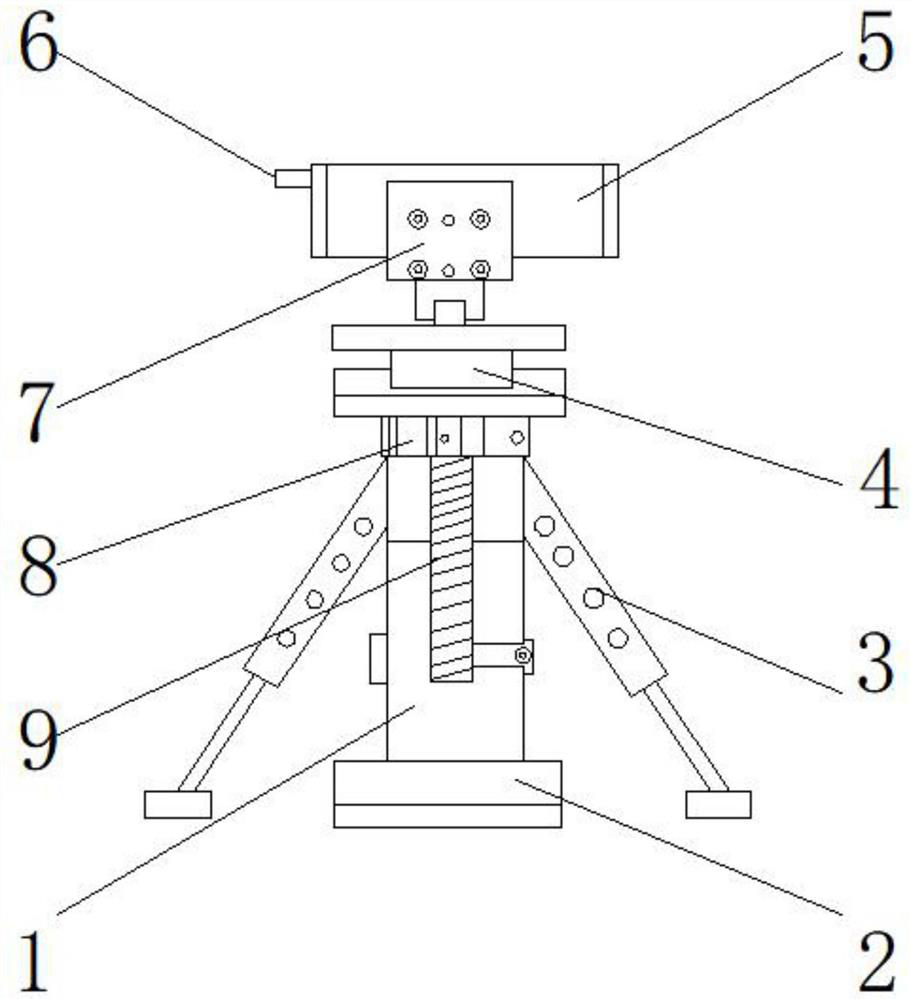
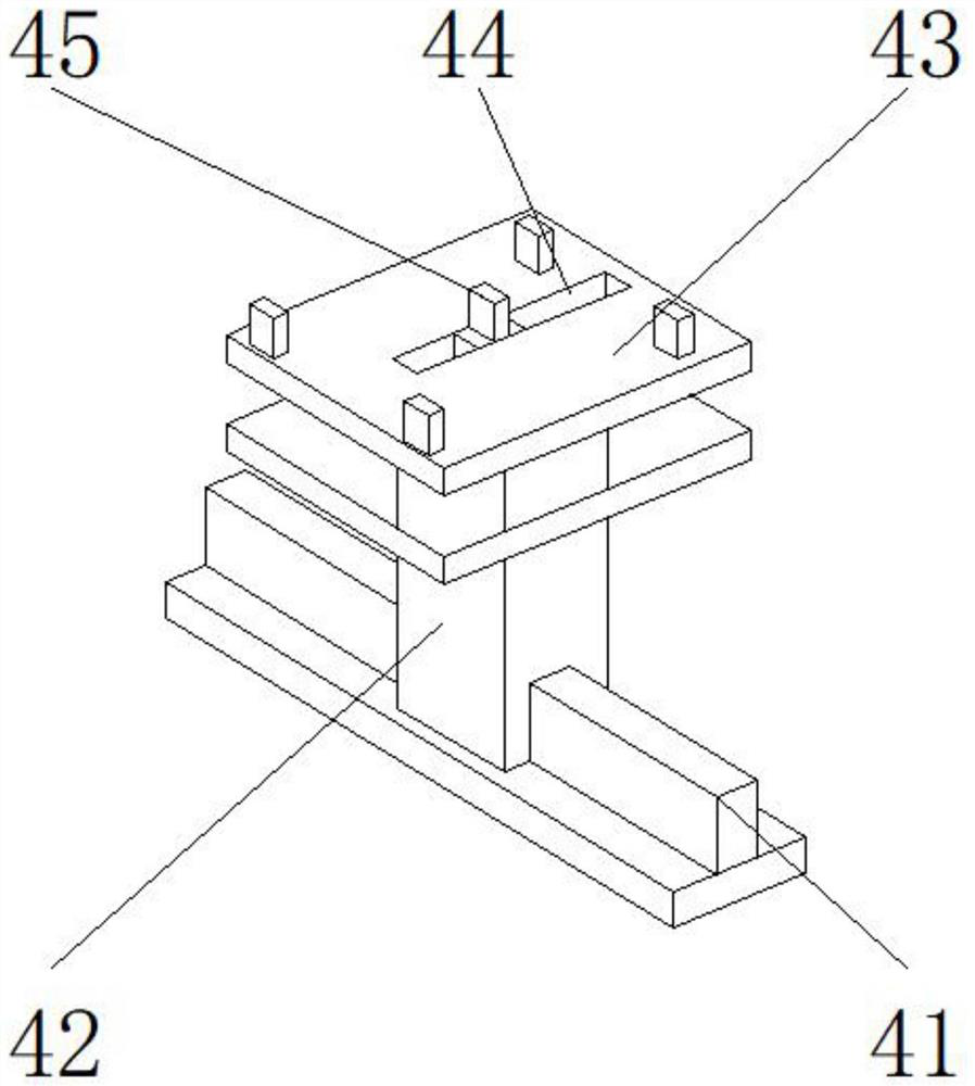
[0027] like Figure 1-5 As shown, the present invention provides a laser measuring device for house measurement, comprising a main body 1, the lower end of the main body 1 of the main body 1 is provided with a weighting device 2, the upper end of the main body 1 is provided with a lifting device 9, and the upper end of the lifting device 9 is provided with A fixing bolt 8 is provided, a support frame 3 is arranged on both sides of the main body 1, an auxiliary positioning device 4 is arranged on the upper end of the fixing bolt 8, a controller 5 is arranged on the upper end of the auxiliary positioning device 4, and a display screen is arranged at the front end of the controller 5 7. A laser transmitter 6 is provided on one side of the controller 5; the auxiliary positioning device 4 includes a sliding block 41, a movable joint 42, a bottom support plate 43, a positioning slot 44, and a clamping block 45, and the sliding block 41 is located in the movable section. The lower en...

Embodiment 2

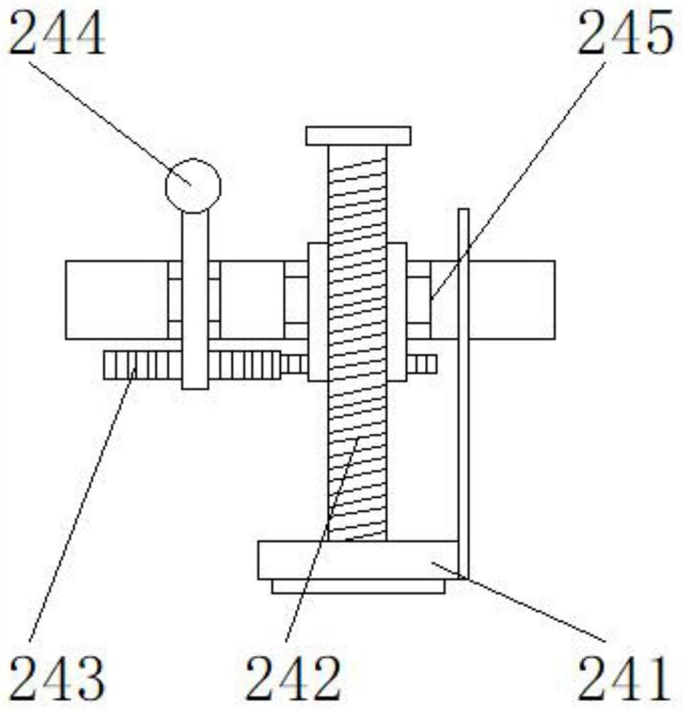
[0030] like Figure 1-5 As shown, on the basis of Embodiment 1, the present invention provides a technical solution: preferably, the weighting device 2 includes a card slot 22, a counterweight block 21, a bottom plate 23, a damping device 24, a connecting shaft 25, and a card slot 22 Located on the outer surface of the upper end of the counterweight block 21, the connecting shaft 25 is located at the front end of the counterweight block 21, the damping device 24 is sleeved on the outer surface of the connecting shaft 25, the bottom plate 23 is located at the lower end of the damping device 24, and the damping device 24 is connected to the outer surface of the connecting shaft 25. A connecting rod is arranged between the bottom plates 23, the upper end of the bottom plate 23 is fixedly connected with the lower end of the damping device 24 through the connecting rod, a connecting hole is provided between the damping device 24 and the connecting shaft 25, and the interior of the d...

Embodiment 3

[0033] like Figure 1-5 As shown, on the basis of Embodiment 1, the present invention provides a technical solution: preferably, the lifting device 9 includes a turning handle 91, a coupling 92, a lifting rod 93, a movable block 94, a latch 95, and a coupling 92 is located at the lower end of the handle 91, the movable block 94 is located below the coupling 92, the lifting rod 93 runs through the movable block 94, the latch 95 is located at the lower end of the lifting rod 93, and a thread is provided between the turning handle 91 and the lifting rod 93 The lower end of the handle 91 is detachably connected to the upper end of the lifting rod 93 through the threaded groove, a notch is provided between the latch 95 and the lifting rod 93, and the upper end of the latch 95 is detachable from the lower end of the lifting rod 93 through the notch connect.

[0034] In this embodiment, the measuring device can be freely adjusted to its height to improve its practicability. By rotat...


PUM


Abstract

The invention discloses a laser measuring device for house measurement, and relates to the technical field of house measurement, and the laser measuring device comprises a main body, the lower end of the main body is provided with a weighting device, the upper end of the main body is provided with a lifting device, the upper end of the lifting device is provided with a fixing bolt, and the two sides of the main body are provided with supporting frames. An auxiliary positioning device is arranged at the upper end of the fixing bolt, and a controller is arranged at the upper end of the auxiliary positioning device. Under the combined action of a sliding strip block, a movable joint, a bottom supporting plate, a positioning clamping groove and a clamping block, the horizontal position of the controller and the horizontal position of the laser transmitter can be adjusted at any time, so that the controller and the laser transmitter can reach the best measurement position, the measurement accuracy is improved, and through the combined action of a rotating handle, a coupler, a lifting rod, a movable block and a clamping bolt, the measurement accuracy is improved. The height of the measuring device can be freely adjusted, and the practicability of the measuring device is improved.

Description

technical field [0001] The invention relates to the technical field of house measurement, in particular to a laser measurement device for house measurement. Background technique [0002] With the development of society, the use of laser measuring devices is becoming more and more extensive. Traditional tool measurement does not have the ability to measure multiple data at the same time, and is prone to errors. The area instrument is used to calculate the data that needs to be measured, so as to obtain the results of distance, length and area, which are used by the industry, especially in the field of housing measurement now more frequently. The following problems exist for the prior art: [0003] 1. The existing laser measuring device for house measurement is not stable enough when placed on the ground, and is easy to shake; [0004] 2. The existing laser measuring device for house measurement cannot change the position of the measuring device, resulting in a decrease in m...

Claims


Application Information

Patent Timeline
IPC IPC(8): G01B11/02G01B11/28
CPCG01B11/02G01B11/28
Inventor 岳丹
Owner 岳丹
Why Eureka
Try Eureka