Concave shaping device for end part of linear motor coil

A coil end, linear motor technology, used in electromechanical devices, manufacturing motor generators, electrical components, etc., can solve the problem of improving the safety protection effect of inconvenient devices, improving the stability effect of inconvenient devices, and clamping and fixing inconvenient device parts, etc. problems, to achieve the effect of improving the effect of processing illumination, improving the convenience of automation, and improving the effect of safety protection

Pending Publication Date: 2022-06-28
浦谷机电科技(苏州)有限公司
View PDF0 Cites 0 Cited by
  • Summary
  • Abstract
  • Description
  • Claims
  • Application Information

AI Technical Summary

Problems solved by technology

[0005] In order to make up for the shortcomings of the existing technology, it is not convenient to improve the stability effect of the device, it is not convenient to improve the safety protection effect of the device, it is not convenient to improve the lighting clarity of the device, and it is not convenient to improve the device components. Fixing problem

Method used


Image

  • Concave shaping device for end part of linear motor coil
  • Concave shaping device for end part of linear motor coil
  • Concave shaping device for end part of linear motor coil

Examples


Embodiment 1

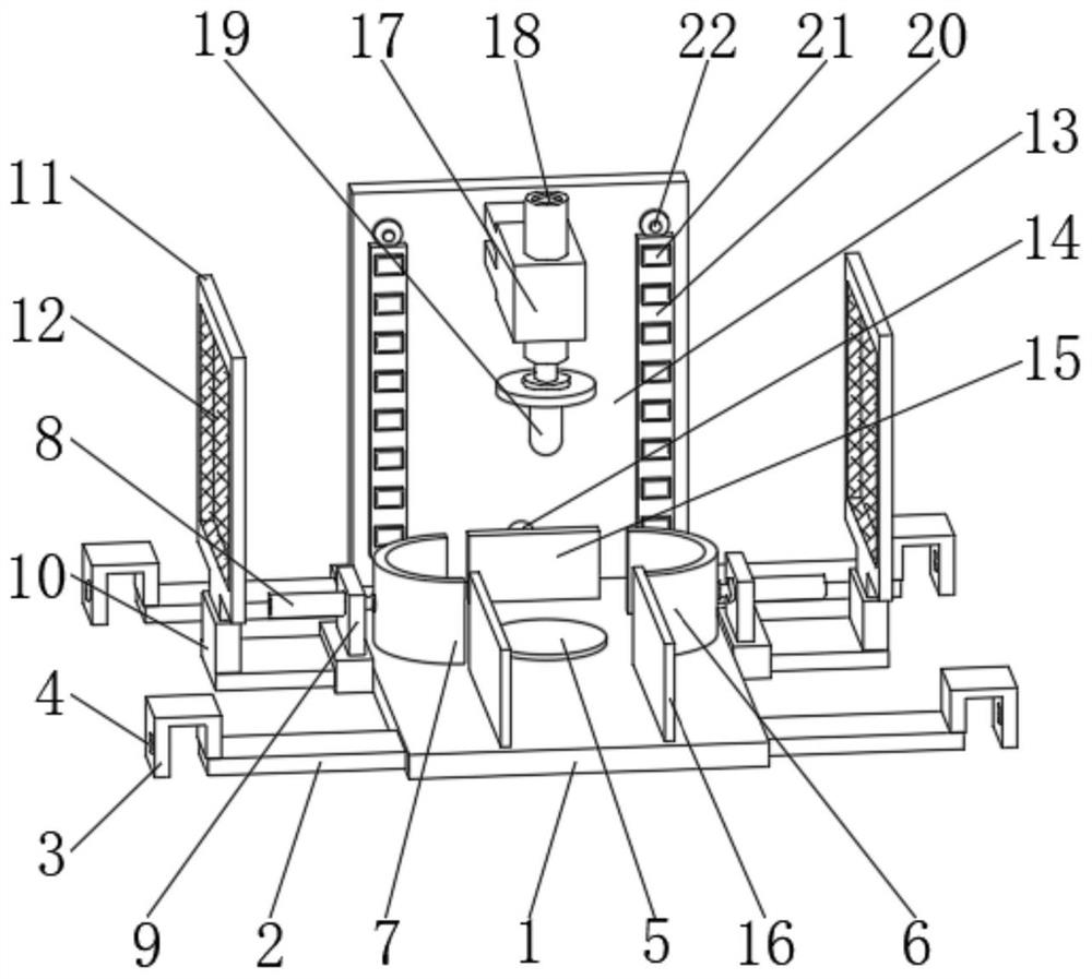
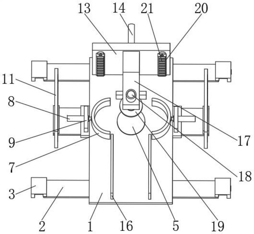
[0027] see figure 1 and Figure 5 As shown, a concave shaping device for the coil end of a linear motor includes a base 1, a connecting plate 10 and a back plate 13. An extension plate 2 is provided on the side of the base 1, and the end of the extension plate 2 is provided with a connecting plate 3. , and the inner side of the connecting plate 3 is provided with a fixing hole 4, the middle position of the base 1 is provided with a positioning plate 5, and the side of the positioning plate 5 is provided with a first arc-shaped plate 6, and the first arc-shaped plate 6 is about the positioning plate 5. The other side is provided with a second arc-shaped plate 7, and the side of the second arc-shaped plate 7 is fixedly connected with an electric telescopic rod 8, and the outer side of the electric telescopic rod 8 is provided with a fixed plate 9, and the connecting plate 10 is arranged on the extension A fixing frame 11 is provided on the side of the board 2 and on the top of ...

Embodiment 2

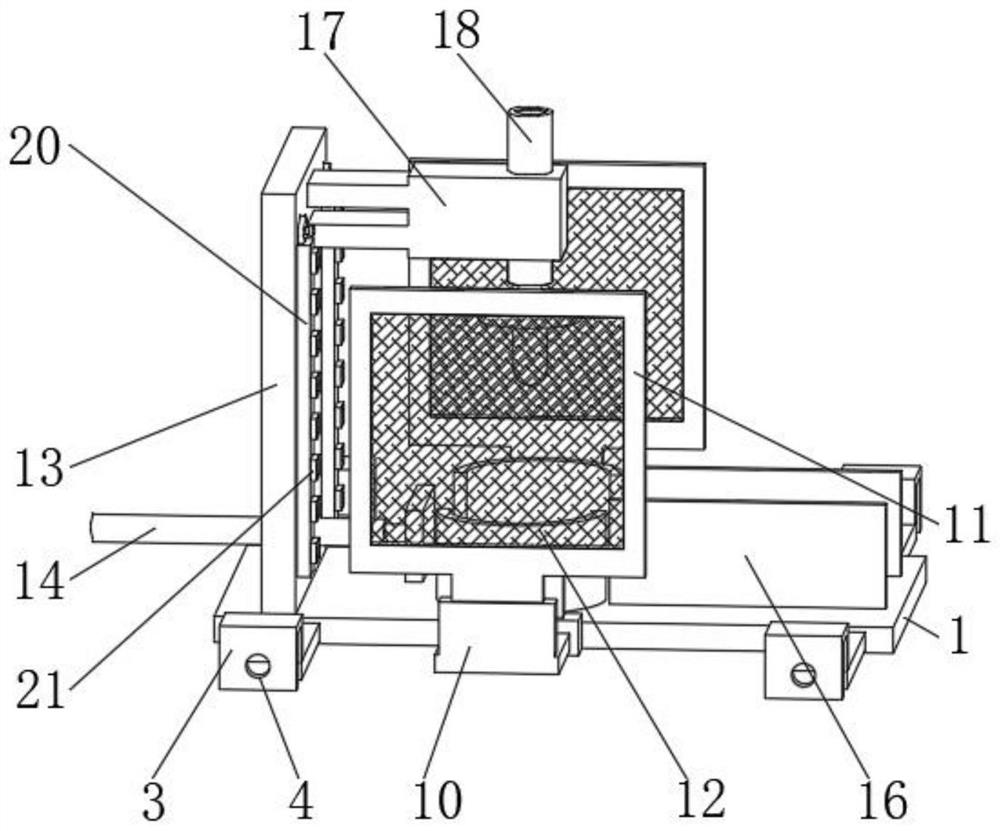
[0032] see Figure 1-4 As shown in the comparison example 1, as another embodiment of the present invention, the back plate 13 is arranged on the back of the base 1, and the inner side of the back plate 13 is penetrated by a hydraulic rod 14, and the end of the hydraulic rod 14 is provided with a push plate 15, and the side of the push plate 15 is provided with a limit plate 16 that is fixedly connected to the base 1, the middle position of the outer wall of the back plate 13 is provided with a fixed seat 17, and the middle position of the end of the fixed seat 17 is provided with a lifting rod 18, And the end of the lifting rod 18 is fixedly connected with the shaping head 19, the side of the fixing seat 17 is provided with a sticking board 20, and the outer wall of the sticking board 20 is provided with a lighting lamp 21, and the top of the sticking board 20 is provided with the back plate 13. Attached set screw 22.

[0033] The push plate 15 forms a lifting structure with...


PUM


Abstract

The invention belongs to the field of shaping devices, and particularly relates to a linear motor coil end concave shaping device which comprises a base, a connecting plate and a back plate, an extension plate is arranged on the side of the base, a connecting plate is arranged at the end of the extension plate, a fixing hole is formed in the inner side of the connecting plate, and a positioning disc is arranged in the middle of the base. A first arc-shaped plate is arranged on the edge side of the positioning disc, a second arc-shaped plate is arranged on the other side, relative to the positioning disc, of the first arc-shaped plate, an electric telescopic rod is fixedly connected to the edge side of the second arc-shaped plate, a fixing plate is arranged on the outer side of the electric telescopic rod, and the connecting plate is arranged on the edge side of the extension plate. A fixing frame is arranged at the top of the connecting plate; according to the device, the stability effect of the device is conveniently improved, the safety protection effect of the device is conveniently improved, the illumination definition of the device is conveniently improved, and device parts are conveniently clamped and fixed.

Description

technical field [0001] The invention relates to the field of shaping devices, in particular to a concave shaping device for a coil end of a linear motor. Background technique [0002] Coil usually refers to a wire winding in a toroidal shape. The most common coil applications are: motors, inductors, transformers, and loop antennas. Introduction A coil in a circuit refers to an inductor. The guide wires are wound one by one, and the wires are insulated from each other. The insulating tube can be hollow, or it can contain an iron core or a magnetic powder core. After the coil is wound, its uniformity needs to be improved. Only one winding of the effective side of the coil is embedded in each stator slot, so the total number of coils is only half of the total number of slots in the motor. The advantages of single-layer winding are that the number of winding coils is relatively simple; there is no interlayer insulation, so the utilization rate of the slot is improved; the sing...

Claims


Application Information

Patent Timeline
Patent Type & Authority Applications(China)
IPC IPC(8): H02K15/04H02K15/00
CPCH02K15/0435H02K15/00
Inventor 刘洪波
Owner 浦谷机电科技(苏州)有限公司
Why Eureka
Try Eureka