
LED module based on rapid replacement of LED lamp bead module

A technology of LED modules and LED lamps, which is applied in the parts of lighting devices, semiconductor devices of light-emitting elements, cooling/heating devices of lighting devices, etc., which can solve the inconvenience of replacing lamp beads and the quality of LED lamps control, complex steps and other issues, to achieve the effect of increasing complexity, ensuring service life and increasing adsorption

Pending Publication Date: 2022-07-01
丁召英
View PDF14 Cites 1 Cited by
  • Summary
  • Abstract
  • Description
  • Claims
  • Application Information

AI Technical Summary

Problems solved by technology

[0003] During the use of LED module lamps, due to long-term use as a light source, and the environment in which the lamp body is used has changes in humidity, temperature, and other factors, and the quality of the LED lamp itself during production cannot be guaranteed. Control, in the middle of the use of the lamp body, some lamp beads inside the LED module will malfunction, and when replacing the existing LED module, the general operation is to disassemble the lamp body as a whole or the lampshade. The steps are complicated, and the overall replacement of the light strip makes the original good LED lamp beads need to be replaced, which is not only wasteful, but also makes the entire lamp bead replacement steps inconvenient and slow in efficiency

Method used


Image

  • LED module based on rapid replacement of LED lamp bead module
  • LED module based on rapid replacement of LED lamp bead module
  • LED module based on rapid replacement of LED lamp bead module

Examples


Embodiment Construction

[0037] The technical solutions in the embodiments of the present invention will be clearly and completely described below with reference to the accompanying drawings in the embodiments of the present invention. Obviously, the described embodiments are only a part of the embodiments of the present invention, rather than all the embodiments. Based on the embodiments of the present invention, all other embodiments obtained by those of ordinary skill in the art without creative efforts shall fall within the protection scope of the present invention.

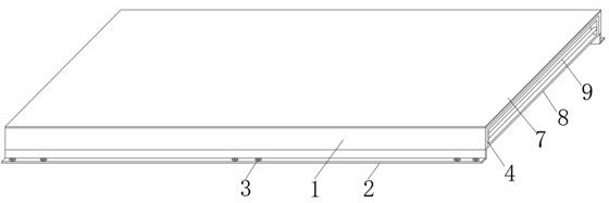
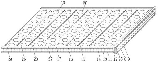
[0038] like Figure 1-7 As shown, the present invention provides a technical solution: an LED module based on the rapid replacement of LED lamp bead modules, comprising; It is clipped into its interior, and a metal grille is arranged below it to circulate and exchange the air inside the LED lamp. A metal mesh is arranged in the metal grille to block dust. The square metal shell includes lamp housing 1, lamp housing 1 The front and r...


PUM


Abstract

The invention relates to the technical field of LED lamps, and discloses an LED module based on quick replacement of LED lamp bead modules. And the square metal shell is provided with a square embedding opening in the upper portion and used for clamping the light-transmitting lamp plate into the square metal shell, and a metal grating is arranged below the square metal shell. When a single LED lamp bead breaks down, the lamp bead body is pulled outwards, the LED lamp element assembly on the lamp bead body is separated from the lamp bead groove, then the annular magnetic sleeve and the magnetic block are magnetically separated, the conductive contact rod inserted into the insertion groove can be separated from the power-on element in the lamp bead body in a power-off mode, and at the moment, the lamp bead body is pulled outwards, and the LED lamp element assembly on the lamp bead body is separated from the power-on element in the lamp bead body. The whole lamp bead can be detached, in this way, the faulted lamp body is taken down, then the operation of replacing the lamp bead is achieved, meanwhile, in the using process of the heat dissipation plate on the LED lamp element assembly, heat generated by the lamp body can be fully conducted, then the single lamp bead on the whole LED has the self-heat-dissipation function, and the service life of the whole LED lamp is prolonged. In this way, the convenience of the LED lamp can be improved, and the service life of the LED lamp beads can be prolonged.

Description

technical field [0001] The invention relates to the technical field of LED lamps, in particular to an LED module based on rapid replacement of LED lamp bead modules. Background technique [0002] LED modules are widely used in LED products. There are also great differences in structure and electronics. The simple thing is to use a circuit board and shell with LEDs to become an LED module. Together with some control, the constant current source and associated heat dissipation treatments make LED life and luminous intensity better. [0003] In the process of using the LED module lamp, due to the long-term use as a light source, and the environment in which the lamp body is used has changes in humidity, temperature, and other factors, and the quality of the LED lamp itself cannot be improved in terms of production. In the mid-term use of the lamp body, some lamp beads inside the LED module may fail. When replacing the existing LED module, the general operation is to disassembl...

Claims


Application Information

Patent Timeline
Patent Type & Authority Applications(China)
IPC IPC(8): F21S8/00F21V29/503F21V29/89F21V31/00F21V21/116F21V19/00F21Y105/12F21Y115/10
CPCF21S8/036F21V29/503F21V29/89F21V19/0035F21V31/005F21V21/116F21V19/0025F21Y2105/12F21Y2115/10
Inventor 丁召英
Owner 丁召英
Learn More