
Switching device with reduced partial discharge and improved three-phase point characteristics

A partial discharge and shaft technology, which is applied in the direction of horizontally pulling isolated switchgear, switchgear parts, electric switches, etc., can solve the problems of accelerated aging and breakdown of insulators, achieve optimized shape and positioning, and minimize local The effect of discharge

Pending Publication Date: 2022-07-01
SCHNEIDER ELECTRIC USA INC
View PDF0 Cites 0 Cited by
  • Summary
  • Abstract
  • Description
  • Claims
  • Application Information

AI Technical Summary

Problems solved by technology

Partial discharges have been shown to occur at such triple points and can lead to accelerated aging and breakdown of insulation

Method used


Image

  • Switching device with reduced partial discharge and improved three-phase point characteristics
  • Switching device with reduced partial discharge and improved three-phase point characteristics
  • Switching device with reduced partial discharge and improved three-phase point characteristics

Examples


Embodiment Construction

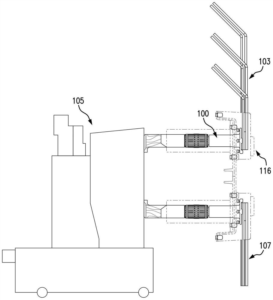
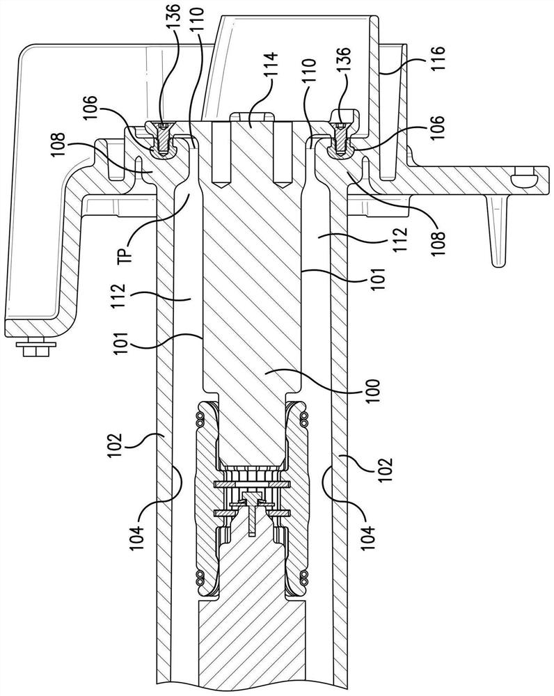
[0036] Figure 1Ais an overall view of a medium voltage circuit breaker 105 with a first primary plug bus 100 connected to the column bus 103 and a second primary plug bus connected to the load bus 107 . The medium voltage circuit breaker may be rated for a maximum voltage of, for example, from 5 to 15 kV, a continuous current rating of, for example, from 1200 to 2000 amperes, and a mains frequency of, for example, 60 Hz. The clusters of fingers are shown electrically connecting the conductors or primary patch bus 100 to the return conductors, which are connected to the main contacts of the circuit breaker. The primary patch bus 100 is a cylindrical conductor that can be connected to the disc plate 114 ( Figure 1B ) cast as a single piece. The puck is electrically connected to the column bus 103 to power the circuit breaker. The annular insulating sleeve 102 and insulating sleeve 116 may be formed as a one-piece insulator that may be Figure 1B ) to the external support st...


PUM


Abstract

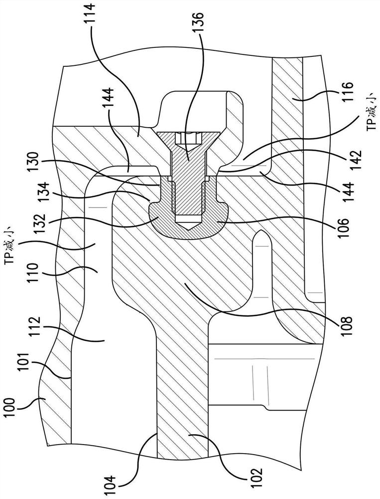
The draw-out circuit breaker has reduced partial discharge in the insulator around the primary bus. A disk plate at one end of the bus includes a threaded insert at a radially separated distance from the bus. An insulating sleeve surrounding the bus is formed to enclose the threaded insert. A raised embossing on the disk plate separates an end portion of the insulating sleeve from an inwardly facing surface of the disk plate by a gap distance. The increased gap distance reduces the formation of a three-phase point region between the surface of the disk plate and the insulating sleeve, thereby reducing the occurrence of partial discharge near the gap in the insulating sleeve.

Description

[0001] CROSS-REFERENCE TO RELATED APPLICATIONS [0002] This application claims the benefit of, and priority to, US Provisional Application No. 63 / 131,412, filed December 29, 2020, at 35 U.S.C. 119(e), which is incorporated herein by reference in its entirety. technical field [0003] The present disclosure relates to reducing the occurrence of partial discharges in insulation to reduce insulation degradation over time and avoid potential major equipment damage. Background technique [0004] By applying an externally applied electric field across the insulator, a discharge is created in the insulator that is high enough to accelerate the insulator's electrons to ionization energy that ionizes the insulator's neutral atoms and molecules during avalanche construction. An insulator externally exposed to very high electric field strengths will break down its body in a discharge. However, insulators exposed to lower electric field strengths may also be damaged if they contain an...

Claims


Application Information

Patent Timeline
Patent Type & Authority Applications(China)
IPC IPC(8): H01H1/58H01H9/00H02B11/12
CPCH01H1/5866H01H9/00H02B11/12H02B11/04H01B17/56
Inventor E.阿瓦洛斯奥蒂兹P.韩F.金蒂尔斯S.弗洛雷斯M.维利福德D.多斯桑托斯
Owner SCHNEIDER ELECTRIC USA INC
Learn More