

Resource allocation method and device
A resource allocation and resource technology, applied in wireless communication, using return channels for error prevention/detection, electrical components, etc., can solve problems affecting the quality of data stream service, and achieve the effect of improving communication effectiveness
- Summary
- Abstract
- Description
- Claims
- Application Information
AI Technical Summary
Problems solved by technology
Method used
Image

Examples
Embodiment 1
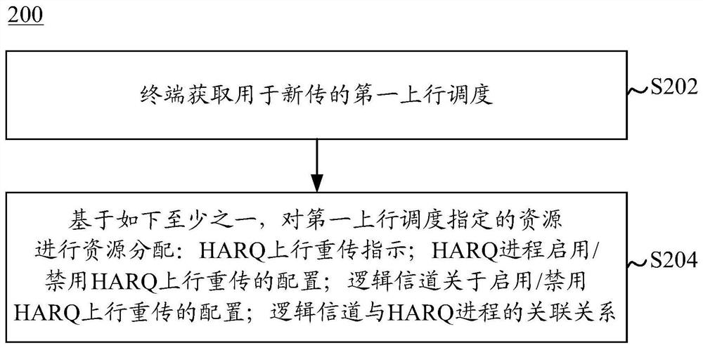
[0068] In this embodiment, the terminal (UE) judges based on the HARQ uplink retransmission indication associated with the first uplink scheduling in the scheduling signaling (such as DCI) and the configuration of enabling / disabling HARQ uplink retransmission for each logical channel of the terminal. It can be multiplexed to the logical channel of the MAC PDU corresponding to the first uplink scheduling, that is, to determine which logical channel data is allowed to be transmitted on the resources specified by the first uplink scheduling. This embodiment includes the following steps:
[0069] Step 1: The UE obtains the following information:
[0070] 1) the first uplink scheduling of the UE;
[0071] 2) The HARQ uplink retransmission indication associated with the first uplink scheduling, the HARQ uplink retransmission indication is used for one of the following: indicating that the first uplink scheduling is for scheduling the transmission for which HARQ uplink retransmission...
Embodiment 2
[0086] In this embodiment, the UE determines that it can be multiplexed to the first HARQ process ID based on the HARQ uplink retransmission configuration for each HARQ process, the HARQ uplink retransmission configuration for each logical channel, and the HARQ process ID indicated by the scheduling signaling. The logical channel of the MAC PDU corresponding to the uplink scheduling, that is, judging the logical channel data allowed to be transmitted on the resource specified by the first uplink scheduling, this embodiment includes the following steps:
[0087] Step 1: The UE obtains the following information:
[0088] 1) the first uplink scheduling of the UE;
[0089] 2) The first HARQ process scheduled by the first uplink scheduling, the first HARQ process is identified by the first HARQ process ID, and the first HARQ process corresponds to the target HARQ process in the foregoing embodiment.
[0090] In an example, in step 1, the UE monitors the downlink control channel to...
Embodiment 3
[0103] In this embodiment, the UE determines the logical channel that can be multiplexed into the MAC PDU corresponding to the first uplink scheduling based on the association relationship (or mapping relationship) between the logical channel and the HARQ process ID, and the HARQ process ID indicated by the UE scheduling signaling , this embodiment includes the following steps:
[0104] Step 1: The UE obtains the following information:
[0105] 1) the first uplink scheduling of the UE;
[0106] 2) The first HARQ process scheduled by the first uplink scheduling, the first HARQ process is identified by the first HARQ process ID, and the first HARQ process corresponds to the target HARQ process in the foregoing embodiment.
[0107] In an example, in step 1, the UE monitors the downlink control channel to obtain scheduling signaling (such as DCI), and the scheduling signaling includes at least the above two contents, and this example is applicable to the scenario of dynamic alloc...
PUM
 Abstract
Description
Claims
Application Information