Industrial control computer case convenient for internal maintenance

A kind of industrial control and computer technology, applied in computing, digital data processing components, instruments, etc., can solve the problems of narrow internal space and inconvenient maintenance of internal computer accessories, and achieve the effect of simple structure, convenient maintenance and easy maintenance

Pending Publication Date: 2022-07-05
SUZHOU INDAL PARK INST OF SERVICES OUTSOURCING
View PDF0 Cites 0 Cited by
  • Summary
  • Abstract
  • Description
  • Claims
  • Application Information

AI Technical Summary

Problems solved by technology

[0004] The purpose of the present invention is to solve the disadvantages in the prior art that it is inconvenient to overhaul the internal computer accessories due to the small internal space of the computer case during use, and proposes an industrial machine that is convenient for overhauling the interior. control computer case

Method used


Image

  • Industrial control computer case convenient for internal maintenance
  • Industrial control computer case convenient for internal maintenance
  • Industrial control computer case convenient for internal maintenance

Examples


Embodiment 1

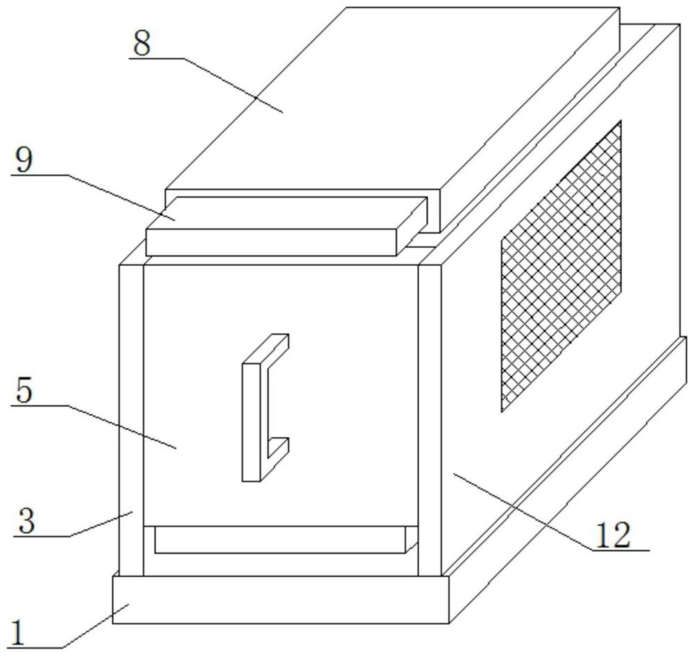
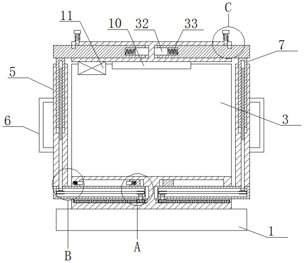
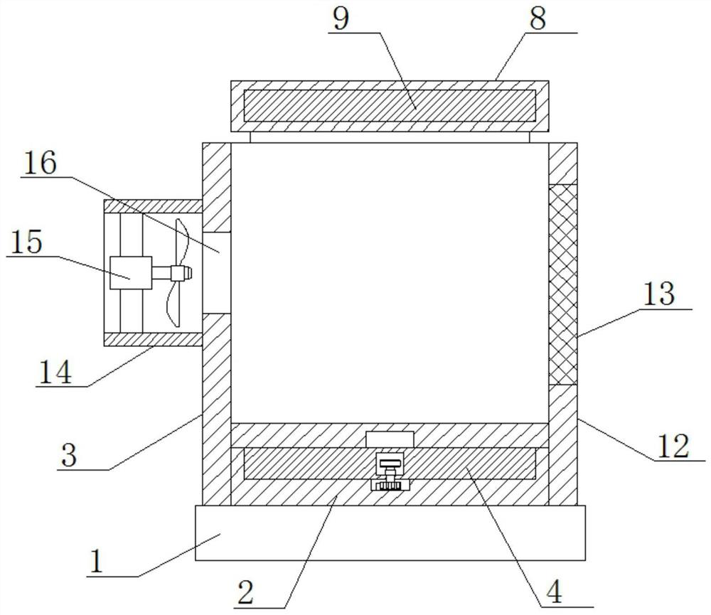
[0027] refer to Figure 1-6 , an industrial control computer case that is convenient for internal maintenance, including a base 1, the top of the base 1 is fixedly mounted with a mounting seat 2 by welding, the top of the base 1 is fixedly installed with a mounting plate 3 by welding, and the two sides of the mounting seat 2 are fixed. Both are provided with a first chute, and a first sliding plate 4 is slidably installed in the two first sliding grooves. The top of the two first sliding plates 4 is fixedly installed with a side plate 5 by welding, and one side of the two side plates 5 is fixed. A handle 6 is fixedly installed by welding, a box door 12 is hinged on one side of the side plate 5, a second chute is opened on the top of the two side plates 5, and a lifting mechanism is arranged in the two second chute. A vertical plate 7 is slidably installed in the second chute, the tops of the two vertical plates 7 are fixedly installed with a second sliding plate 9 by welding, ...

Embodiment 2

[0036] The difference from the first embodiment is: the top of the base 1 is fixedly installed with the mounting seat 2 by welding, the top of the base 1 is fixedly installed with the mounting plate 3 by welding, and both sides of the mounting seat 2 are provided with first chute, A first sliding plate 4 is slidably installed in the two first sliding grooves, a side plate 5 is fixedly installed on the top of the two first sliding plates 4 by welding, and a handle 6 is fixedly installed on one side of the two side plates 5 by welding. A box door 12 is hinged on one side of the side plate 5, a second chute is provided on the top of the two side plates 5, a lifting mechanism is arranged in the two second chute, and the two second chute are slidably installed There are vertical plates 7, the tops of the two vertical plates 7 are fixedly installed with a second sliding plate 9 by welding, the outer sides of the two second sliding plates 9 are slidably installed with the same top pla...


PUM


Abstract

The invention belongs to the field of computer cases, particularly relates to an industrial control computer case convenient for internal maintenance, and provides the following scheme aiming at the problem that internal computer accessories are inconvenient to maintain due to narrow internal space of an existing computer case in the use process: the industrial control computer case comprises a base, a mounting seat is fixedly mounted at the top of the base through welding, a mounting plate is fixedly mounted at the top of the base through welding, first sliding grooves are formed in the two sides of the mounting seat, first sliding plates are slidably mounted in the two first sliding grooves, and side plates are fixedly mounted at the tops of the two first sliding plates through welding; a handle is fixedly mounted on one side of each side plate through welding, and a box door is hinged to one side of each side plate. In the use process, the size of the internal space of the computer case can be adjusted, so that internal computer accessories can be conveniently overhauled, and the computer case is simple in structure and convenient to use.

Description

technical field [0001] The invention relates to the technical field of computer cases, in particular to an industrial control computer case which is convenient for internal maintenance. Background technique [0002] Computers have dramatically changed our lives in the last few decades. In industry, the computer has also been applied accordingly, which is the industrial computer. The so-called industrial computer, in simple terms, is the application of the computer in the industry, and it is precisely because of the application in the industry that the industrial computer and the ordinary computer have different characteristics. As a part of computer accessories, the main function of the chassis is to place and fix various computer accessories, and play a supporting and protective role. [0003] In the prior art, during the use of the computer case, due to its small internal space, it is inconvenient to repair the internal computer accessories. For this reason, we propose a...

Claims


Application Information

Patent Timeline
IPC IPC(8): G06F1/18G06F1/20
CPCG06F1/183G06F1/206
Inventor 张书锋尤澜涛刘正潘娜
Owner SUZHOU INDAL PARK INST OF SERVICES OUTSOURCING
Why Eureka
Try Eureka