Top sealing device for sealing top of electronic equipment and sealing piece of top sealing device

A technology of electronic equipment and sealing devices, which is applied in the field of top sealing devices and their seals, can solve the problems of single sealing structure function, poor sealing and maintainability, and achieve good maintainability, good compression performance, and convenient disassembly and assembly.

Pending Publication Date: 2022-07-08
CHINA AVIATION OPTICAL-ELECTRICAL TECH CO LTD
View PDF0 Cites 0 Cited by
  • Summary
  • Abstract
  • Description
  • Claims
  • Application Information

AI Technical Summary

Problems solved by technology

[0003] With the continuous upgrading of weapons and equipment, the functions of various electronic equipment are gradually increasing, and they are developing in the direction of modularization and integration, while the power and heat consumption of electronic equipment are also increasing. The form of heat dissipation and cooling can no longer meet its heat dissipation requirements. It is necessary to carry out heat dissipation and cooling in the form of forced ventilation cooling. The upper and lower ventilation of electronic equipment is one of the forms of heat dissipation design. It is often necessary to seal the ventilation system of electronic equipment with the outside world. The air inlet is installed with an air filter to dehumidify and desalt the environmental control air. How to realize the sealing design of the ventilation system of electronic equipment will have an important impact on the safe and reliable use of electronic equipment. , but the sealing structure in the existing ventilation system has a single function, poor sealing and maintainability, and it is difficult to meet the demand

Method used


Image

  • Top sealing device for sealing top of electronic equipment and sealing piece of top sealing device
  • Top sealing device for sealing top of electronic equipment and sealing piece of top sealing device
  • Top sealing device for sealing top of electronic equipment and sealing piece of top sealing device

Examples


Embodiment Construction

[0030] The technical solutions of the present invention will be further described in detail below with reference to the accompanying drawings and preferred embodiments.

[0031] An embodiment of a top sealing device for top sealing of electronic equipment:

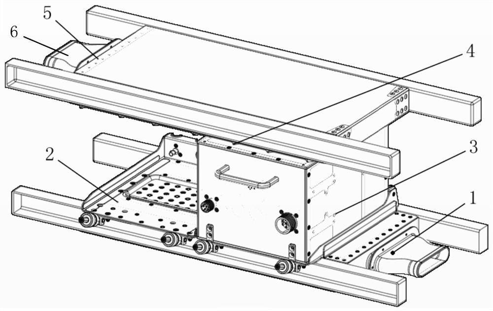
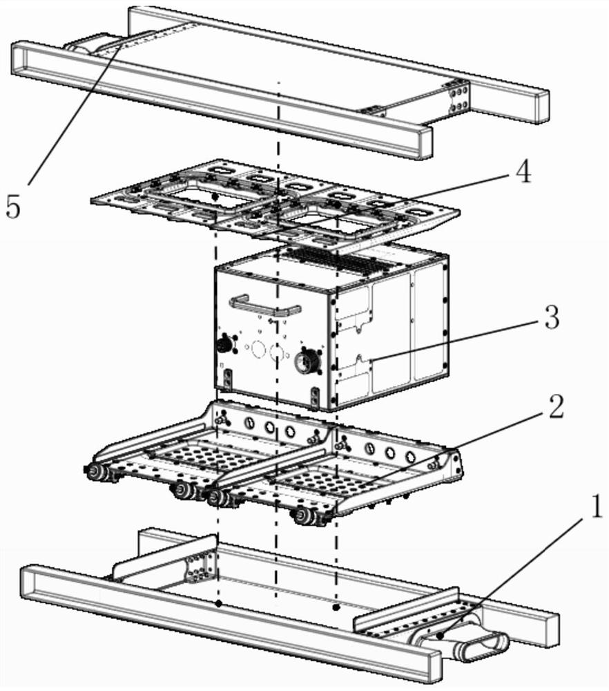
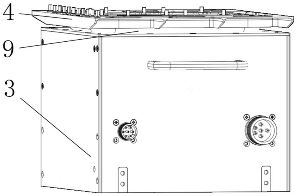
[0032] see Figure 1 to Figure 10 , a top sealing device for the top sealing of electronic equipment, the top sealing device 4 is arranged between the top ventilation system 5 and the top of the electronic equipment 3, and is used to realize the sealing between the top of the electronic equipment chassis and the top ventilation system. The electronic device 3 is installed on the mounting bracket 2 in a pluggable manner along the front and rear directions, and the mounting bracket 2 is fixed on the bottom ventilation system 1 . The top ventilation system includes a load-bearing frame and an air duct plate. There are two load-bearing frames and are arranged in parallel. The air duct plate is roughly in the shape of a U-shap...


PUM


Abstract

The invention relates to a top sealing device used for sealing the top of electronic equipment and a sealing piece thereof.The top sealing device is arranged between a top ventilation system and the top of the electronic equipment and comprises a support, the sealing piece and a pressing plate, the support is installed at the bottom end of the top ventilation system, and a ventilation hole is formed in the support; the pressing plate is connected with the support through a fastener, the sealing piece is arranged between the pressing plate and the support in a pressing mode, the sealing piece is a sealing rubber ring of an annular hollow cavity structure, and the sealing piece is used for making elastic contact with the top of the electronic equipment so as to achieve sealing between the top ventilation system and the electronic equipment. By means of the technical scheme, the sealing piece is good in compression performance and large in elastic deformation, the effective contact area of the sealing face is large, the sealing performance is improved, the ventilation sealing effect between the top of the electronic equipment and a top ventilation system is improved, the insertion and extraction force can be effectively reduced when the electronic equipment is installed, and the maintainable performance of the sealing device is improved.

Description

technical field [0001] The invention belongs to the technical field of aerospace electrical equipment, and particularly relates to a top sealing device used for top sealing of electronic equipment and a sealing member thereof. Background technique [0002] With the continuous development of naval equipment, the research and development of domestic carrier-based aircraft has developed rapidly. When the airborne electronic equipment flies with the aircraft at low altitudes within the range of the carrier-based platform, it will be eroded by splashing sea water and marine atmosphere. The marine atmosphere contains A large amount of salt, microorganisms and other pollutants, seawater itself is a natural electrolyte, seawater contains a variety of salts, and the resistance in seawater is also very small. At the same time, the airborne electronic equipment is mainly used in carrier-based aircraft. The capacity of the hangar on the aircraft carrier is limited and cannot accommodate...

Claims


Application Information

Patent Timeline
Patent Type & Authority Applications(China)
IPC IPC(8): H05K5/06H05K5/02
CPCH05K5/06H05K5/061H05K5/0213
Inventor 王涛陈建超刘宁胡培根陈学永吕云朋李雪冬杨成博
Owner CHINA AVIATION OPTICAL-ELECTRICAL TECH CO LTD
Why Eureka
Try Eureka