
Air bag type floating loading mechanism
A loading mechanism and airbag-type technology, which is applied in the field of airbag-type floating loading mechanism, can solve the problems of unpublished bridge durability wheel load test device loading mechanism, etc., and achieve the effect of reducing self-weight, reducing running resistance, and authentic experimental data
- Summary
- Abstract
- Description
- Claims
- Application Information
AI Technical Summary
Problems solved by technology
Method used
Image

Examples
Embodiment 1
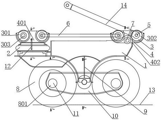
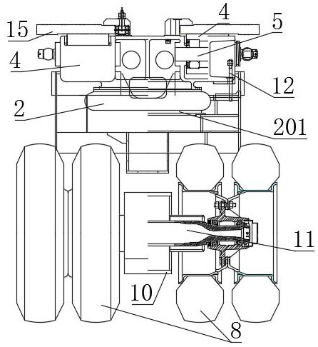
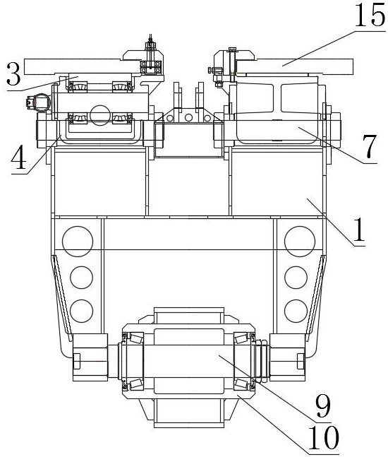
[0033] The upper end of the airbag 2 is sealed and fixed at the bottom of the first loading wheel box seat 401. The left and right ends of the first loading wheel box seat 401 are each supported by two pins through bearings to support the four first loading wheels 301. The lower end of the airbag 2 is connected to the airbag bottom plate. 201 is sealed and seated on the loading body 1. The left and right ends of the first loading wheel box seat 402 are also supported by two pin shafts through bearings, respectively, and the two second loading wheels 302 are supported. The first loading wheel box seat 402 is hinged to the upper surface of the loading body 1 through the shaft pin sensor 7 101; One end of the bridge deck reaction force of the loading body 1 is applied by the rolling wheel 8, the suspension, the loading body 1, the airbag bottom plate 201, the airbag 2, the first loading wheel box seat 401, the pin shaft, the bearing, and the first loading wheel 301 On the track, ...
PUM
 Abstract
Description
Claims
Application Information