Balance weighing structure and balance weighing method for horizontal rotating construction of box girder bridge

A construction method and technology of box girders, which are applied in bridges, bridge construction, erection/assembly of bridges, etc., can solve problems that can only be installed on the top of bridge piers, increase jacking force, and concrete crushing, so as to ensure normal operation and erection. The effect of small jacking force and reduced running resistance

Active Publication Date: 2015-03-25
CHINA RAILWAY MAJOR BRIDGE ENG GRP CO LTD +1
View PDF6 Cites 16 Cited by
  • Summary
  • Abstract
  • Description
  • Claims
  • Application Information

AI Technical Summary

Problems solved by technology

However, in this case, conventional column piers cannot be used, M-shaped or door-shaped frame piers must be used, and the turntable can only be set on the top of the pier to cross non-parallel double-deck roads
The size of the frame-type piers along the bridge direction is small. If a jack is directly installed between the upper and lower parts of the turntable, the jacking force arm will be short, resulting in a large jacking force. If the T structure is unbalanced, the jacking force will be further increased. increase, and a larger jacking force may cause concrete collapse at the jacking point, resulting in damage to the bridge and a huge safety risk

Method used


Image

  • Balance weighing structure and balance weighing method for horizontal rotating construction of box girder bridge
  • Balance weighing structure and balance weighing method for horizontal rotating construction of box girder bridge
  • Balance weighing structure and balance weighing method for horizontal rotating construction of box girder bridge

Examples


Embodiment Construction

[0028] The present invention will be described in further detail below in conjunction with the accompanying drawings and embodiments.

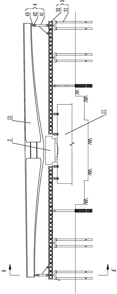
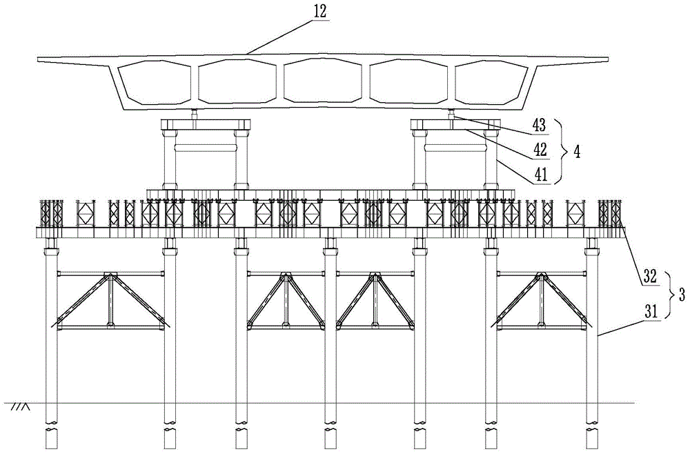
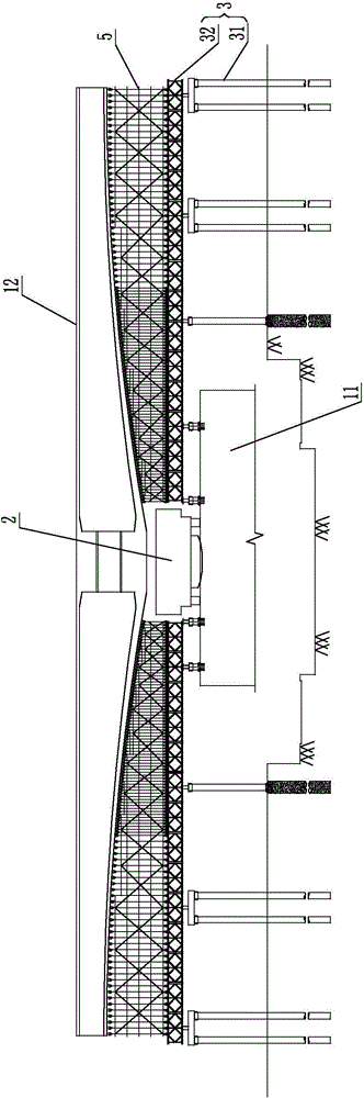
[0029] like figure 1 and figure 2 As shown, a balance weighing structure for the horizontal swivel construction of a box girder bridge is arranged on the T structure of the box girder bridge before the swivel body. The T structure of the box girder bridge includes a pier 11 and a main girder 12, and the pier 11 is M-shaped or door Form frame type, the pier 11 is arranged vertically on the ground, and the main girder 12 is arranged above the pier 11 horizontally. The balance weighing structure includes a turntable 2, two sets of lower brackets 3 and two sets of auxiliary weighing systems 4, the turntable 2 is arranged on the top surface of the bridge pier 11, and is located at the center of the bottom surface of the main girder 12, and the two sets of lower brackets 3 and Two sets of auxiliary weighing systems 4 are respectively symmetricall...


PUM


Abstract

The invention relates to the technical field of bridge construction, in particular to a balance weighing structure and a balance weighing method for horizontal rotating construction of a box girder bridge. A rotation plate is arranged on the top of a pier and in the center of the bottom of a girder, each truss is arranged below the girder along the length direction of the girder, one end of each truss is fixed onto the top of the pier, and the other end of each truss is erected on the ground through a vertical column; each group of auxiliary weighing systems is positioned between the end, in the length direction, of the girder and the truss at the same end. The method includes: arranging a lower support and an upper support on two sides of the pier, and casting the girder in situ on the rotation plate and the two groups of upper supports; demounting part of the upper supports, and arranging the auxiliary weighing systems between the end of the girder and the lower supports at the same end; performing balance test, and balancing to enable a center of gravity of the girder to be coincided with the center of the rotation plate; rotating the rotation plate to complete construction. The balance weighing structure and the balance weighing method for horizontal rotating construction of the box girder bridge have the advantages that a T structure is adjusted to a balanced state, directly jacking on the rotation plate is avoided, and the bridge is protected from damages owing to low jacking force.

Description

technical field [0001] The invention relates to the technical field of bridge construction, in particular to a balance weighing structure and method for horizontal swivel construction of a box girder bridge. Background technique [0002] Generally, the horizontal swivel construction of box girder bridge first divides the continuous box girder bridge into multiple independent box girder bridge T structures from the mid-span, makes (prefabricated or poured) brackets by using the terrain, sets a turntable at the pier, and weighs the bridge through the weighing system. The center of gravity of the T structure is repeatedly tested, and the T structure is adjusted to a balanced state by means of additional counterweight. The center of gravity basically falls on the rotation center of the turntable. Helong. [0003] The common horizontal swivel construction of box girder bridge adopts the method of pier bottom swivel. In this way, the turntable is set between the cap and the botto...

Claims


Application Information

Patent Timeline
Patent Type & Authority Applications(China)
IPC IPC(8): E01D21/08
CPCE01D21/08
Inventor 潘东发涂满明毛伟琦马涛陈治任高庚元刘玲晶杨蒙陈明辰胡文静张遵明刘志燕梁伟田继开曲江峰
Owner CHINA RAILWAY MAJOR BRIDGE ENG GRP CO LTD
Why Eureka
Try Eureka