
Clamp and workbench assembly

A workbench and fixture technology, applied in the direction of manufacturing tools, workpiece clamping devices, etc., can solve problems such as affecting the use of fixtures

Pending Publication Date: 2022-07-19
HANGZHOU UNITED ELECTRIC MFG CO LTD
View PDF1 Cites 0 Cited by
  • Summary
  • Abstract
  • Description
  • Claims
  • Application Information

AI Technical Summary

Problems solved by technology

However, although this kind of fixture is suitable for most use scenarios, in some special use scenarios, the operation part will interfere with the structure to be clamped or other external structures, which will affect the use of the fixture

Method used


Image

  • Clamp and workbench assembly
  • Clamp and workbench assembly
  • Clamp and workbench assembly

Examples


Embodiment Construction

[0022] The technical solutions in the embodiments of the present invention will be clearly and completely described below with reference to the accompanying drawings in the embodiments of the present invention. Obviously, the described embodiments are only a part of the embodiments of the present invention, but not all of the embodiments. Based on the embodiments of the present invention, all other embodiments obtained by persons of ordinary skill in the art without creative efforts shall fall within the protection scope of the present invention.

[0023] It should be noted that when a component is referred to as being "connected to" another component, it can be directly connected to the other component or an intervening component may also exist. When a component is considered to be "set on" another component, it may be directly set on the other component or there may be a co-existing centered component. When a component is said to be "fixed" to another component, it may be di...


PUM


Abstract

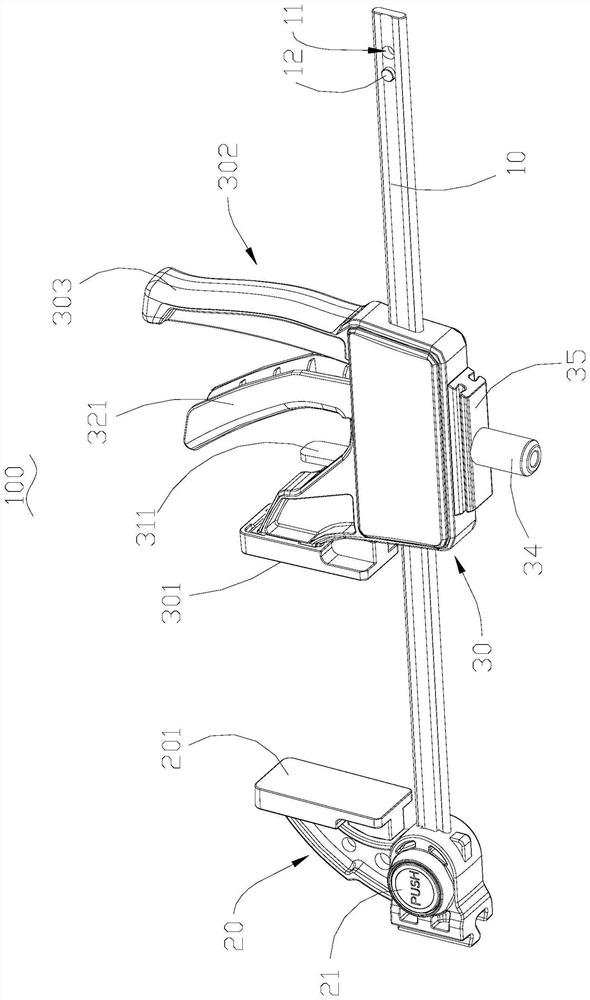
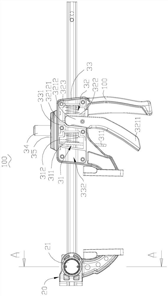
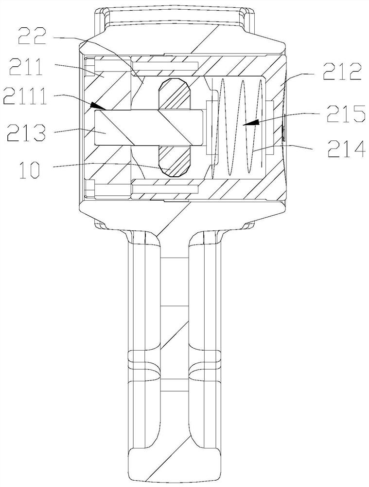
The clamp comprises a rod body, a fixed clamp body and a movable clamp body, the fixed clamp body is fixedly arranged on the rod body, and the movable clamp body is movably installed on the rod body; the fixed clamp body comprises a first clamping surface, the movable clamp body is provided with a second clamping surface, and the first clamping surface and the second clamping surface are matched with each other and can clamp an external structure; the movable clamp body further comprises an operation part, and the position of the movable clamp body on the rod body can be adjusted through the operation part. The operation part and the second clamping face are located on the same side of the rod body. According to the clamp, the operation part and the second clamping face are located on the same side of the rod body, position interference between the operation part and the to-be-clamped structure in the use process of the clamp can be avoided, and meanwhile user operation is facilitated.

Description

technical field [0001] The invention relates to the field of operating tools, in particular to a fixture and a workbench assembly. Background technique [0002] The clamp usually has two clamping surfaces, one of which is the fixed end, and the other is the movable end, and the user can adjust the position of the movable end through the operation part. In a traditional clamp, such as patent CN211388387U, the operation part and the two clamping surfaces are on different sides. However, although this kind of fixture is suitable for most usage scenarios, in some special usage scenarios, the operating part will interfere with the structure to be clamped or other external structures, which affects the use of the fixture. SUMMARY OF THE INVENTION [0003] In view of this, it is necessary to provide a fixture and a workbench assembly. [0004] The invention provides a clamp, comprising a rod body, a fixed clamp body and a movable clamp body, the fixed clamp body is fixed on the...

Claims


Application Information

Patent Timeline
Patent Type & Authority Applications(China)
IPC IPC(8): B25B11/00
CPCB25B11/00
Inventor 李井建
Owner HANGZHOU UNITED ELECTRIC MFG CO LTD
Learn More