
Double-pendulum centrifugal rotation traction machine

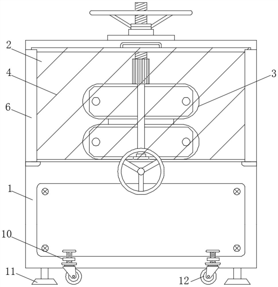
A tractor and double pendulum technology, applied in the field of tractors, can solve the problems of being easily affected by the outside, not convenient for transfer, inconvenient to move, etc., and achieve the effects of improved protection, strong functionality and strong practicability

Pending Publication Date: 2022-07-19
徐州欣派斯净水设备有限公司
View PDF0 Cites 0 Cited by
  • Summary
  • Abstract
  • Description
  • Claims
  • Application Information

AI Technical Summary

Problems solved by technology

[0005] Aiming at the deficiencies of the prior art, the present invention provides a double-pendulum centrifugal rotary tractor, which solves the problem that most of the existing double-pendulum centrifugal rotary tractors on the market have a completely exposed double-pendulum structure when they are used. In order to facilitate the inspection and maintenance of the staff at any time, there are no protective measures on the outside, and the exposed structure is easily affected by external influences during operation. For example, foreign objects from the outside fly into the interior of the tractor and the double pendulum structure occurs Collision will produce different degrees of negative effects, and there are certain limitations in use. At the same time, most centrifugal rotary tractors are inconvenient for the staff to move them during use, and they are not convenient enough during transfer. Flexible movement in the field, and at the same time, it needs to maintain its stability after the movement. It cannot be compatible with the two, and it is more troublesome to use.

Method used


Image

  • Double-pendulum centrifugal rotation traction machine
  • Double-pendulum centrifugal rotation traction machine
  • Double-pendulum centrifugal rotation traction machine

Examples


Embodiment Construction

[0022] The technical solutions in the embodiments of the present invention will be clearly and completely described below with reference to the accompanying drawings in the embodiments of the present invention. Obviously, the described embodiments are only a part of the embodiments of the present invention, but not all of the embodiments. Based on the embodiments of the present invention, all other embodiments obtained by those of ordinary skill in the art without creative efforts shall fall within the protection scope of the present invention.

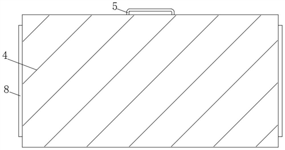
[0023] see Figure 1-4 , the embodiment of the present invention provides a technical solution: a double pendulum centrifugal rotary tractor, including a tractor body 1, a clamping device 6, a baffle 4 and a slider 8, the external fixed connection clip of the tractor body 1 The holding device 6 is provided with a baffle 4 inside the holding device 6 , a slider 8 is arranged outside the baffle 4 , and a chute 7 is provided inside the h...


PUM


Abstract

The double-pendulum centrifugal rotating tractor comprises a tractor body, a clamping device, a baffle and a sliding block, the clamping device is fixedly connected to the exterior of the tractor body, the baffle is arranged in the clamping device, the sliding block is arranged on the exterior of the baffle, a sliding groove is formed in the clamping device, and the sliding block is arranged in the sliding groove. The sliding blocks are movably inserted into the sliding grooves. According to the double-pendulum centrifugal rotation traction machine, the sliding type baffle is arranged outside the traction machine body, the problem that a double-pendulum structure in a traditional rotation traction machine does not have protection measures is well solved, in this way, the baffle can shield the outer portion of a working cavity, and therefore the protection effect in the operation process is achieved; and meanwhile, as the baffle is made of the transparent acrylic material, the sight of a worker cannot be influenced when the rotary traction machine is used, the protection effect of the rotary traction machine on the double-pendulum structure during operation is greatly improved, and the rotary traction machine is simple in overall structure, high in functionality and high in protection performance.

Description

technical field [0001] The invention relates to the technical field of tractors, in particular to a double-pendulum centrifugal rotary tractor. Background technique [0002] Traction motors include traction motors, traction generators, auxiliary motors, crawler pneumatic tractors, rotary tractors, etc., and are usually used in railway trunk line electric locomotives, industrial and mining electric locomotives, electric drive diesel locomotives and various electric vehicles. [0003] Most of the double-pendulum centrifugal rotary tractors on the market are completely exposed when they are applied. During the process, it is easy to be affected by the outside. For example, foreign objects from the outside fly into the interior of the tractor and collide with the double pendulum structure, which will have different degrees of negative impact. There are certain limitations in use. At the same time, most centrifugal The rotary tractor is inconvenient for the staff to move it duri...

Claims


Application Information

Patent Timeline
IPC IPC(8): H02K7/10H02K5/04
CPCH02K7/10H02K5/04
Inventor 乔文连赵敏赵瑞
Owner 徐州欣派斯净水设备有限公司
Learn More