

Square tube frame structure capable of being quickly assembled and disassembled and implementation method of square tube frame structure
A tube frame, assembly and disassembly technology, applied in the field of amusement park frames, can solve the problems of complex connection process, exposed connection flange, low efficiency, etc., and achieve the effects of good overall aesthetics, simple and convenient assembly and disassembly, and quick installation operation.
- Summary
- Abstract
- Description
- Claims
- Application Information
AI Technical Summary
Benefits of technology
Problems solved by technology
Method used
Image

Examples
Embodiment 1
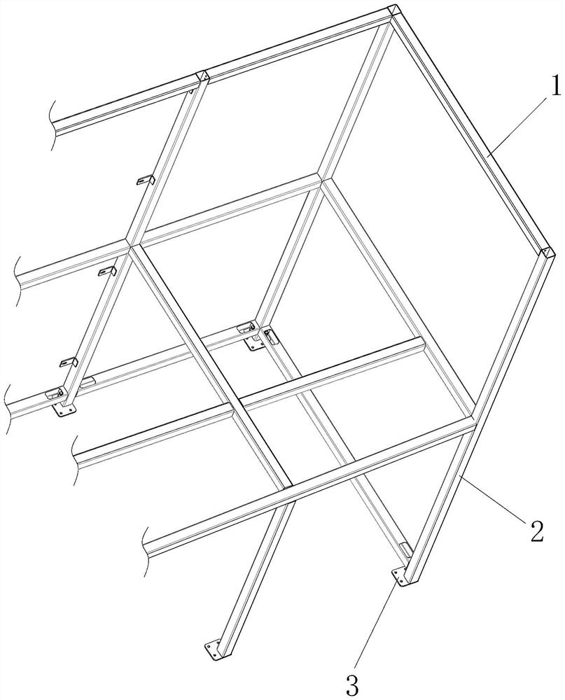
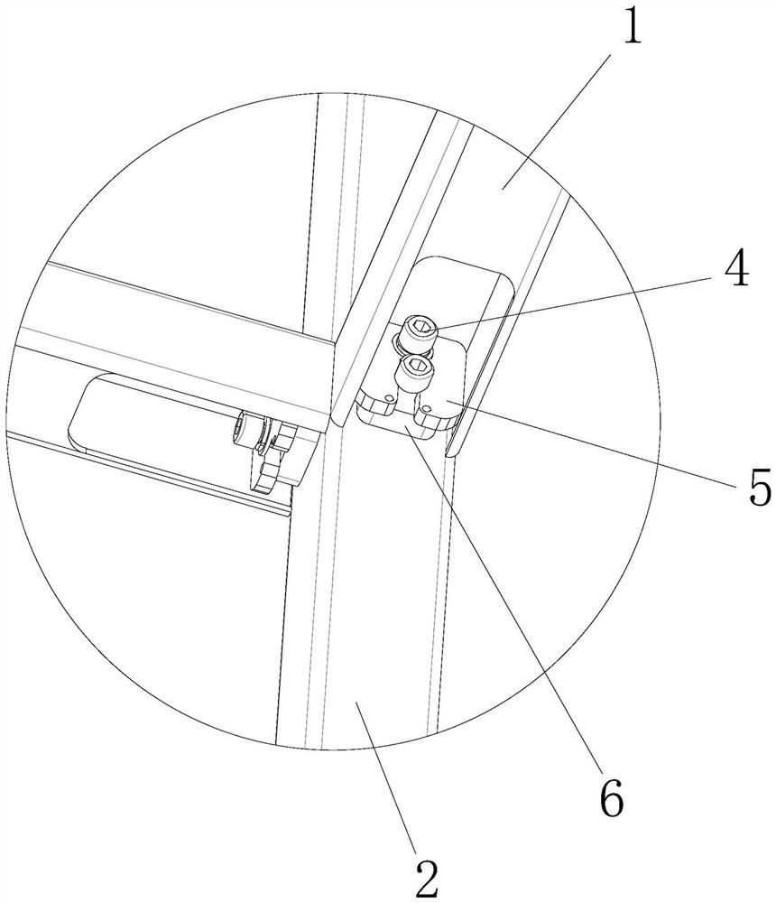
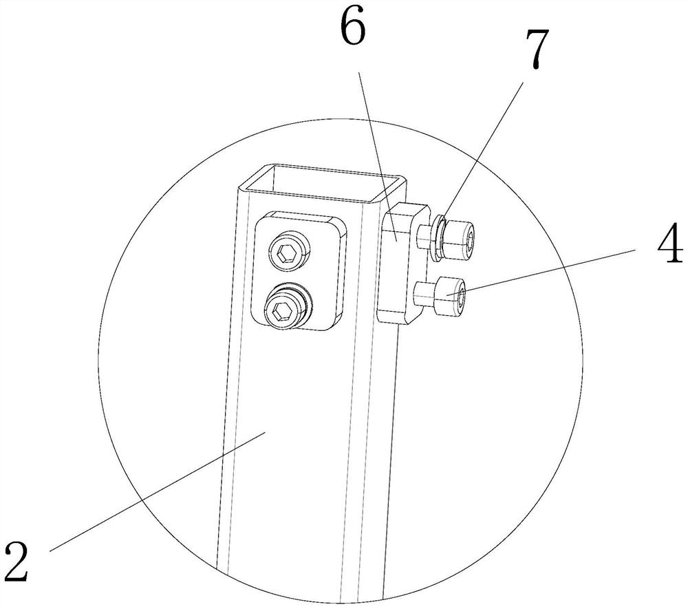
[0038] see Figure 1-6 , the present invention provides the following technical solutions: a square tube frame structure that can be quickly assembled and disassembled, comprising a number of uprights 2 and a beam 1 for connecting a number of uprights 2, a connection block 6 is provided at the connection between the uprights 2 and the crossbeam 1, and the connection The block 6 is a rectangular block corresponding to the inner space of the beam 1. The connecting block 6 is provided with two threaded holes, and bolts 4 are engaged in the threaded holes. The bolts 4 are cylindrical head socket head bolts. The fastener 5 corresponding to the connection block 6 and the side surface of the end of the beam 1 are provided with a first operating slot 8, and the first operating slot 8 is a U-shaped structure.
[0039] By adopting the above technical solution, the connection node between the column 2 and the beam 1 is hidden inside the beam 1, which can provide convenience for the pavin...
Embodiment 2
[0049] The difference between this embodiment and Embodiment 1 is that, specifically, a space is set between the fastener 5 and the end face of the beam 1 , and the length of the space is equal to the thickness of the connecting block 6 .
[0050] By adopting the above technical solution, after the fastener 5 is inserted into the bolt 4, the fastener 5 can be attached to the connection block 6 to ensure the stability of the connection.
Embodiment 3
[0052] The difference between this embodiment and Embodiment 1 is that: specifically, a marking groove 12 is provided below the avoidance hole 11 .
[0053] By adopting the above technical solution, the connecting block 6 is positioned to ensure that the threaded hole corresponds to the avoidance hole 11 after welding.
PUM
 Abstract
Description
Claims
Application Information