Holding device

A technology of clamping device and clamper, which is applied in the direction of fixed installation, configuration/installation of recording head, guidance of recording carrier, etc., which can solve problems such as heavy workload and long time

Inactive Publication Date: 2004-04-28
DEUTSCHE THOMSON-BRANDT GMBH
View PDF0 Cites 0 Cited by
  • Summary
  • Abstract
  • Description
  • Claims
  • Application Information

AI Technical Summary

Problems solved by technology

Existing clamping devices have a large number of individual parts, which take a considerable amount of time to set up due to

Method used


Image

  • Holding device
  • Holding device
  • Holding device

Examples


Embodiment Construction

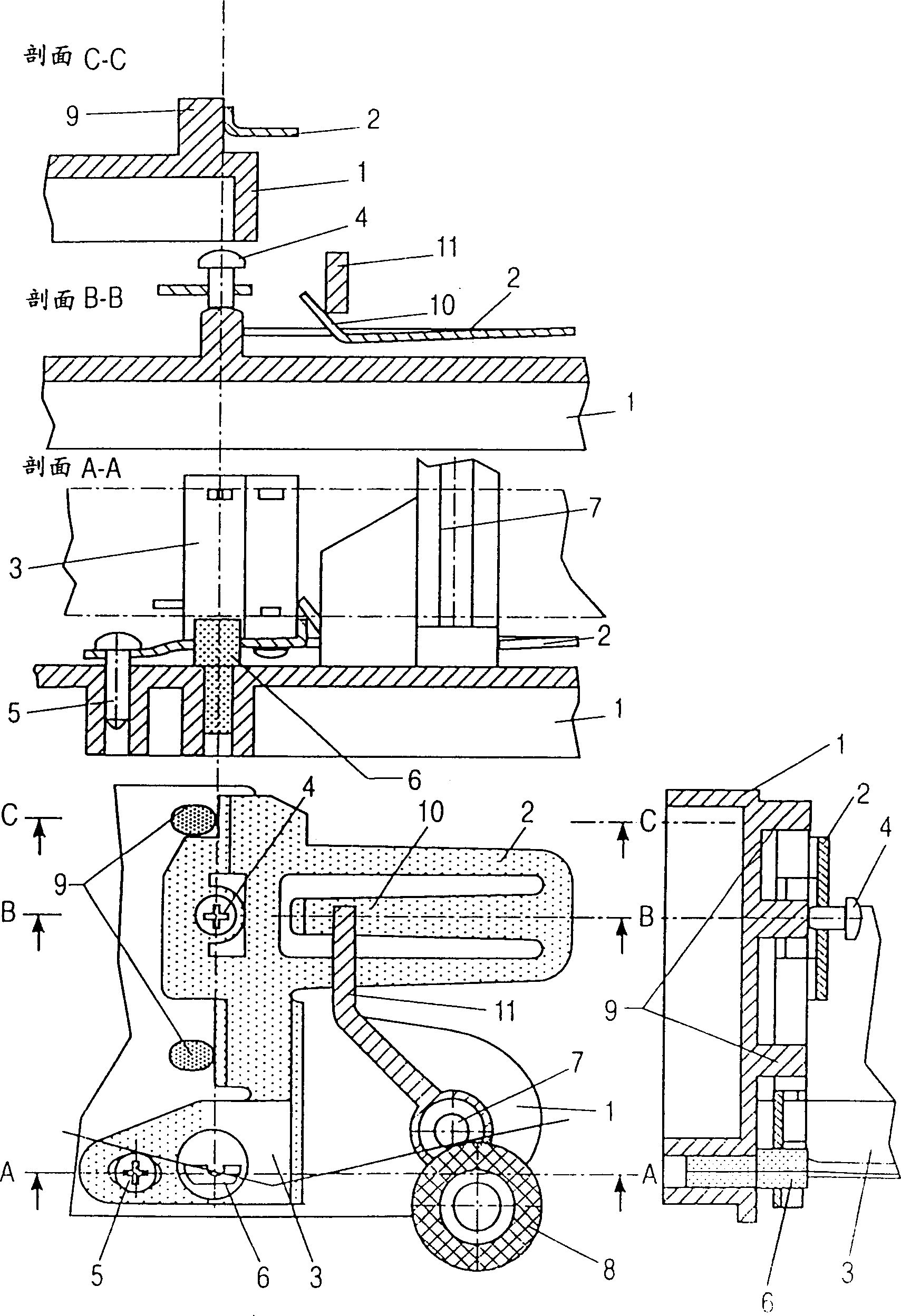
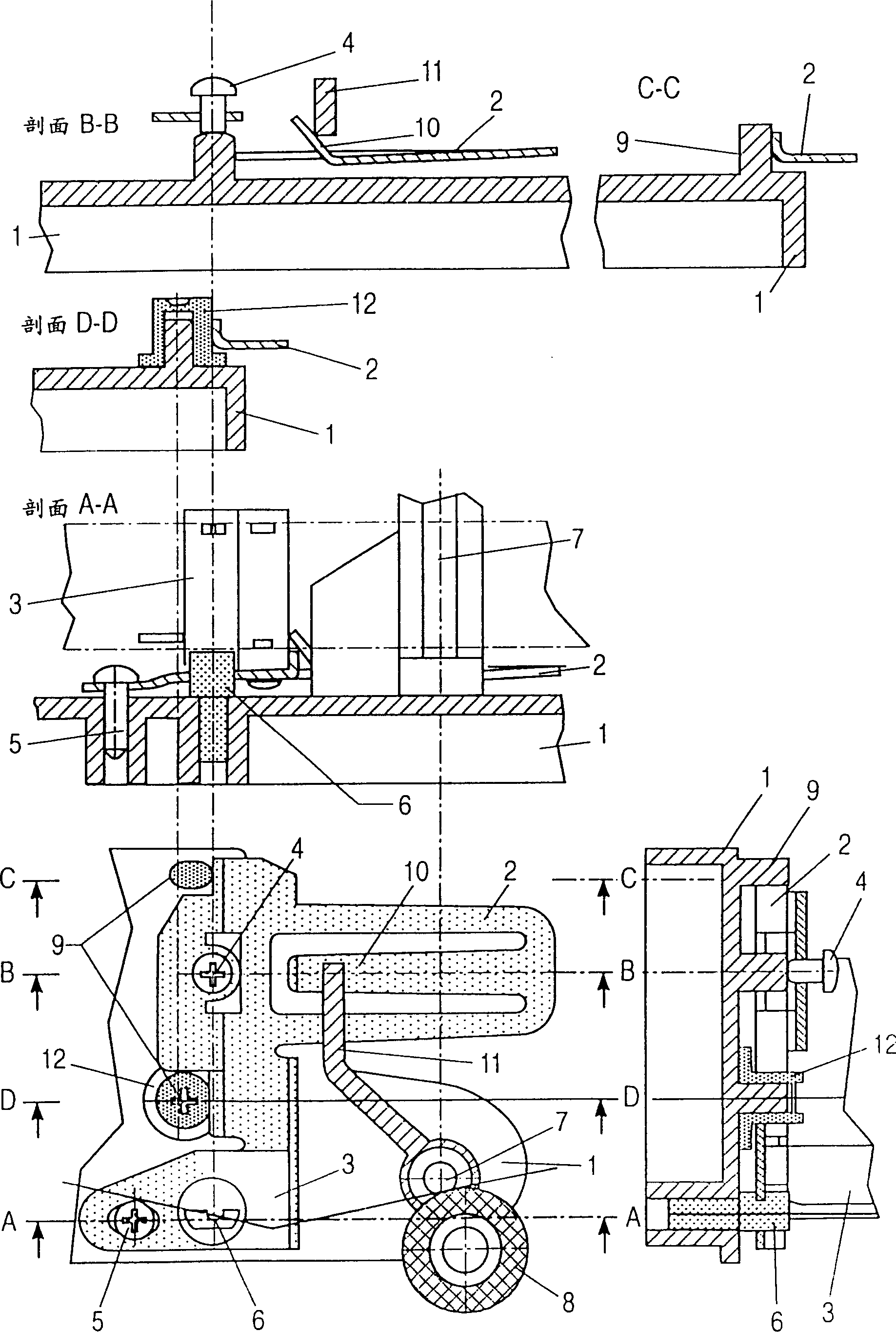
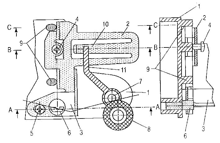
[0017] The holding device illustrated in the drawing comprises a base plate 1 on which the head support plate 2 is fastened in such a manner that the head support plate 2 is adjustable. A capstan 7 with a pinch roller 8 is further installed on the base plate 1 and a clamper 11, a bracket 6 and several stoppers are fastened. exist figure 1 The design shown has two fixed stops 9, whereas according to the figure 2 The design includes a fixed stop 9 and an adjustable stop 12. The head plate 2 has an audio control head 3 . In a region facing away from the stops 9 , 12 , the head carrier plate 2 has a base through which the attachment of the tongue 10 is formed through a groove. The tongue 10 is beveled at its end facing the stops 9 , 12 and engages the holder 11 .

[0018] In that region between the stops 9 , 12 the head plate 2 is penetrated by the screw 4 . The screw 4 is mounted so as to be rotatable in the thread of the head plate 2 and is supported on a boss of the base ...


PUM


Abstract

A holding device for an audio control head of video recorder, which realizes on arrangement significantly saving time using a smaller number of constituent elements without having an arranging manners mutually affecting reach other. A head carrier plate (2) is pressurized by a spring force against a stop (9; 12) is the direction of the longitudinal axis of a video tape. An audio control head is provide with lower end thereof positioned on a supporting member (6) which also functions as a tape guide for a lower end of the video tape. two arranging screws (4) and (5) are only regard for arranging the head carrier plate (2) by a tilt angle with respect to a capstan shaft (7) or a tilt angle with respect to the longitudinal axis of the video tape.

Description

technical field [0001] The invention relates to a clamping device for an audio control head of a video recorder. technical background [0002] In video recorders according to the VHS system, the recording of video signals and stereo audio signals is carried out on inclined tracks by means of a rotating video head, while the recording of control signals and mono audio signals is carried out in longitudinal direction by means of a stationary audio control head. on the track. [0003] To ensure compatibility between VCRs and pre-recorded tapes, the audio control head must be adjusted to the recording track of the tape. For this purpose tape guides at the front and rear of the audio control head and screws and helical springs capable of setting the position of the head plate relative to the base plate and the tape guides and fixing the set position are used. The inclination angle (tilt angle) of the audio control head relative to the drive axis, the inc...

Claims


Application Information

Patent Timeline
IPC IPC(8): G11B5/49G11B5/55G11B5/56G11B15/60G11B15/62
CPCG11B5/56G11B15/602G11B15/62
Inventor 埃哈德·劳伯克劳斯·奥尔德曼弗里茨·韦瑟
Owner DEUTSCHE THOMSON-BRANDT GMBH
Why Eureka
Try Eureka