Plasma jet coupling modular stealth structure

A plasma and coupling module technology, applied to antennas, electrical components, etc., can solve the problems of large target area, irregular shape of surface area, and inability to maintain uniform plasma all the time, and achieve the effect of reducing cost and resource consumption, and being easy to disassemble

Pending Publication Date: 2022-07-22
SHENYANG AEROSPACE UNIVERSITY
View PDF1 Cites 0 Cited by
  • Summary
  • Abstract
  • Description
  • Claims
  • Application Information

AI Technical Summary

Problems solved by technology

However, the disadvantages of the solution provided by the above invention patents are: 1. Due to the large surface area and irregular shape of the ground large-scale equipment target, the plasma cannot completely cover the equipment surface
2. If the large target on the ground moves, the plasma cloaking device that has been installed is inconvenient to disassemble and reinstall
3. Due to the large target area, the plasma formed by the device cannot be sustained uniformly

Method used


Image

  • Plasma jet coupling modular stealth structure
  • Plasma jet coupling modular stealth structure
  • Plasma jet coupling modular stealth structure

Examples


Embodiment 1

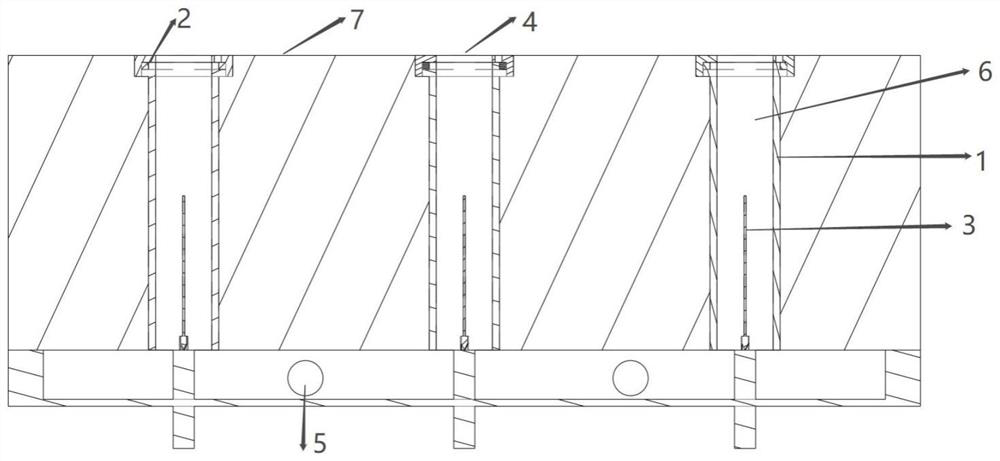
[0039] like Figure 1-7As shown, when the above-mentioned plasma stealth module is realized by the structure a with good fixing effect, it includes a module body, and a plurality of micro-holes are processed in the module body. The inner wall of the micro-hole is an insulating medium layer, and each micro-hole is The top is connected with a negative electrode, the needle-shaped electrode of the positive electrode protrudes into the lower part of the micro-hole, the fixing seat of the needle-shaped electrode passes through the fixing hole at the bottom of the module body, and a spray port is opened on the top of the module body, and the spray port is located above the corresponding negative electrode .

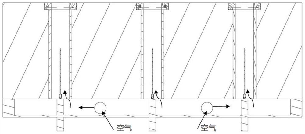
[0040] In order to reduce the resistance of the air and make the air better enter the ionization space in the micropore, the bottom side of the needle-shaped electrode is a pointed structure, which is clamped with the gap of the fixing seat.

[0041] Preferably, the negative e...

Embodiment 2

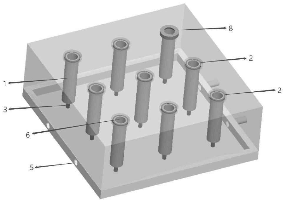
[0045] like Figure 8-13 As shown, when the above-mentioned plasma stealth module is realized by a simple installation structure b, it includes a module body, a plurality of micro-holes are processed in the module body, and a negative plate and an insulating medium layer are sequentially laid on the module body. The negative plate is provided with a through hole at the position of each micro-hole, the top of the through-hole is an injection port arranged on the insulating medium layer, and a needle-shaped electrode is arranged in the lower part of the micro-hole, and the needle-shaped electrode is fixed to the bottom frame connected.

[0046] One side of the negative plate is provided with a negative extension tube, which is inserted into the interior of the adjacent plasma stealth module and is in contact with the negative plate of the module; one side of the fixing frame is provided with a positive extension tube, which is inserted into the phase. It is adjacent to the inte...


PUM


Abstract

The invention discloses a plasma jet coupling modular stealth structure which comprises a plurality of plasma stealth modules laid on the surface of an equipment target and a hose, one end of each plasma stealth module is provided with an outward extending air channel pipe, and the other end of each plasma stealth module is provided with an air hole. Every two adjacent plasma stealth modules are spliced and convey air through matching of the outwards-extending air channel pipes and the air holes. One end of the hose is connected to the outward-extending air channel pipe of one plasma stealth module in a sleeving mode, and the other end of the hose extends into the air hole of the adjacent plasma stealth module. The plasma stealth modules serve as basic units and can be laid to form an array after being spliced, even if the surface area of an equipment target is too large or the shape of the equipment target is irregular, complete coverage can be achieved by controlling the number and layout of the plasma stealth modules, and the desired stealth effect is achieved through the combined action of the multiple modules.

Description

technical field [0001] The invention relates to the technical field of ground target stealth, in particular to a plasma jet coupled modular stealth structure. Background technique [0002] At present, some common physical covering methods are commonly used to hide important targets on the ground, such as finding some dense vegetation, large buildings and other barriers, or applying some absorbing materials on the surface of the target. However, these methods can only play a certain degree of stealth, and cannot actively change their own characteristics according to the changes of the opponent's radar parameters; moreover, the workload is large and the price is expensive; at the same time, if the opponent has a strong radar detection ability, the above-mentioned ordinary methods are almost impossible. does not work. [0003] Plasma stealth, as an active anti-radar stealth technology, can adjust its own parameters in time according to the opponent's monitoring and radar param...

Claims


Application Information

Patent Timeline
Patent Type & Authority Applications(China)
IPC IPC(8): H01Q17/00
CPCH01Q17/00
Inventor 陈雷孙灯磊王保怀杨贺曾文
Owner SHENYANG AEROSPACE UNIVERSITY
Why Eureka
Try Eureka