
Improved cranium drilling device for neurosurgery operation

A technique for neurosurgery and surgery, applied in the field of neurosurgery, can solve the problems of reducing the workload and difficulty of post-cleaning work

Inactive Publication Date: 2022-07-29
PEOPLES HOSPITAL OF HENAN PROV
View PDF0 Cites 0 Cited by
  • Summary
  • Abstract
  • Description
  • Claims
  • Application Information

AI Technical Summary

Problems solved by technology

[0003] In order to solve the above technical problems, the present invention provides an improved cranial drill for neurosurgery, which solves the need to deal with the bone debris generated by the patient's head in real time during the drilling process, and needs to limit its position and reduce its cleaning area. Reduce the workload and difficulty of post-cleanup work

Method used


Image

  • Improved cranium drilling device for neurosurgery operation
  • Improved cranium drilling device for neurosurgery operation
  • Improved cranium drilling device for neurosurgery operation

Examples


Embodiment 1

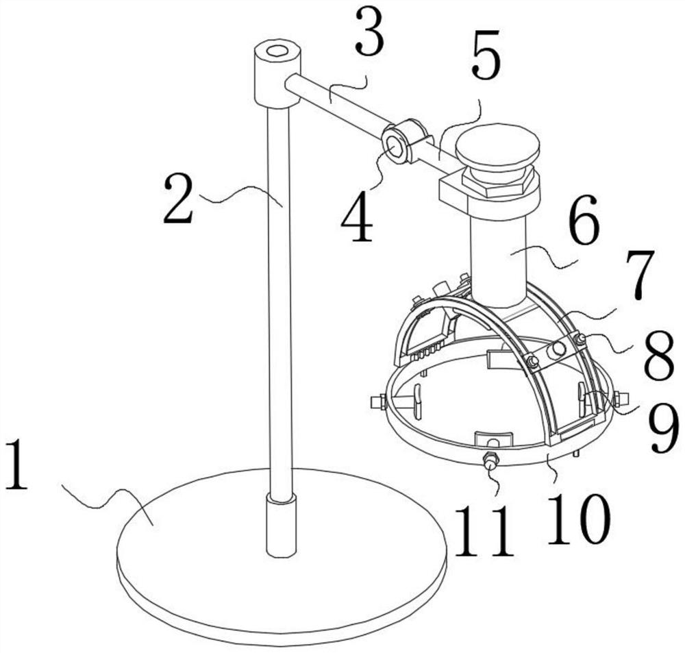
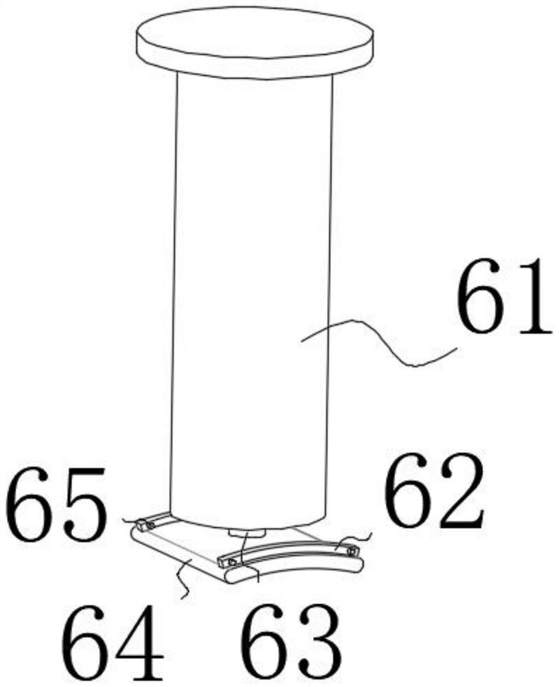
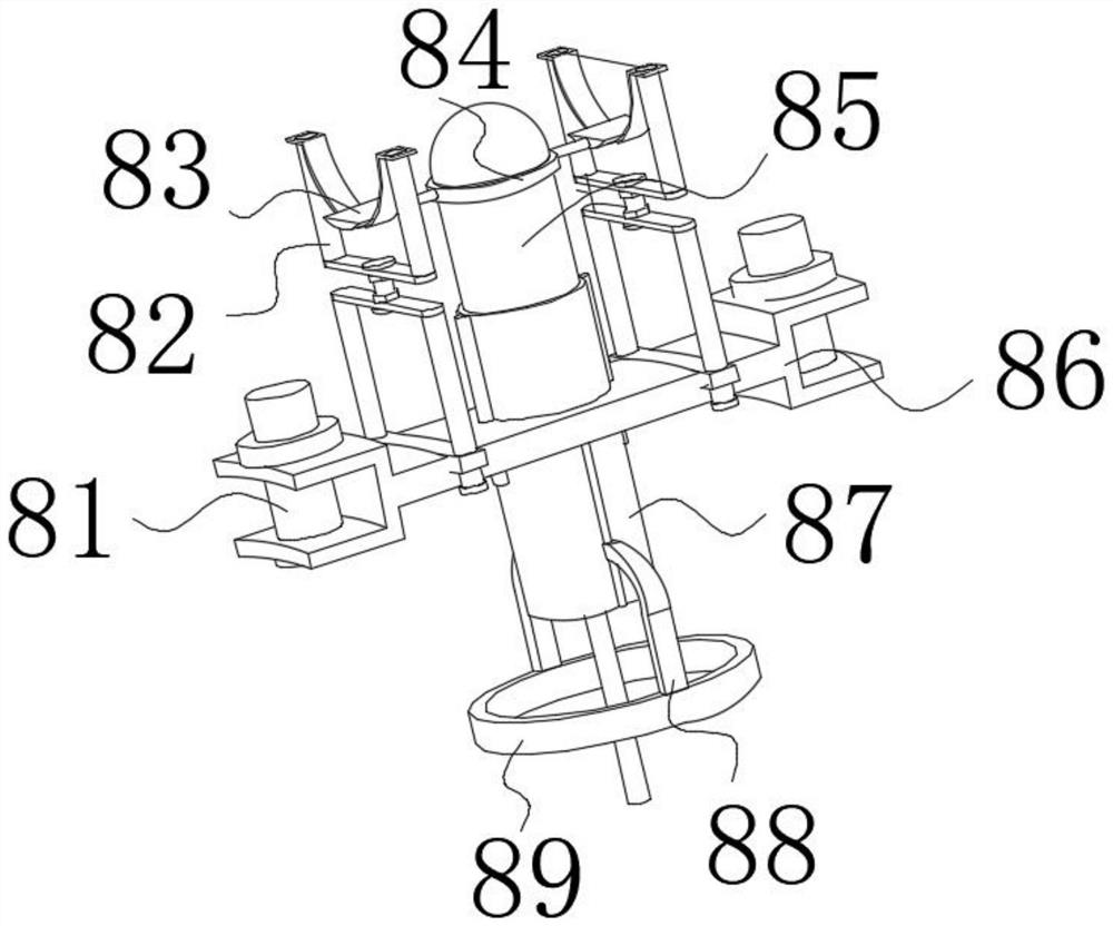
[0028] use Figure 1-Figure 7 An improved cranial drill for neurosurgery according to an embodiment of the present invention will be described as follows.

[0029] like Figure 1-Figure 7 As shown, an improved cranial drill for neurosurgery according to the present invention includes a chassis 1, the top of the chassis 1 is movably connected with a support rod 2, the top of the support rod 2 is provided with a steering rod 3, and the support rod The top of 2 is movably connected with the left end of the steering rod 3, the right end of the steering rod 3 is provided with a rotating column 4, and the right end of the steering rod 3 is movably connected with the outer surface of the rotating column 4, and the outer surface of the rotating column 4 is provided with a positioning rod 5 , and the outer surface of the rotating column 4 is movably connected with the left end of the positioning rod 5. The positioning rod 5 is provided with a clamping device 6 inside. By setting the c...

Embodiment 2

[0037] use Figure 5-Figure 6 An improved cranial drill for neurosurgery according to an embodiment of the present invention will be described as follows.

[0038] like Figure 5-Figure 6 As shown, an improved cranial drill for neurosurgery according to the present invention, on the basis of the first embodiment, the contact device 10 includes a snap ring 101, so that the doctor needs to continuously clear the area during the craniotomy process It is maintained on the top of the patient's forehead, which reduces the difficulty of cleaning up the bone debris generated by the patient's head in real time during the drilling process. The clamping ring 101 is symmetrically provided with a tightening rod 102, and the inner wall of the clamping ring 101 and the tightening rod. The outer surface of 102 is movably connected, the top of the tightening rod 102 is fixedly connected with a pressing plate 106, the interior of the snap ring 101 is evenly provided with a positioning screw 10...


PUM


Abstract

The invention relates to the field of neurosurgical operations, in particular to an improved cranium drilling device for neurosurgical operations, which comprises a chassis, a supporting rod is movably connected to the top of the chassis, a steering rod is arranged at the top of the supporting rod, the top of the supporting rod is movably connected with the left end of the steering rod, and a rotating column is arranged at the right end of the steering rod. The right end of the steering rod is movably connected with the outer surface of the rotating column, a positioning rod is arranged on the outer surface of the rotating column, the outer surface of the rotating column is movably connected with the left end of the positioning rod, a clamping device is arranged in the positioning rod, and the inner wall of the positioning rod is movably connected with the top of the clamping device; according to the improved cranium drilling device for the neurosurgery operation, the problems that in the punching process, bone scraps and the like generated on the head of a patient need to be treated in real time, the bone scraps and the like need to be limited, the cleaning area of the bone scraps and the like needs to be reduced, and the workload and the working difficulty of later cleaning work are reduced are solved.

Description

technical field [0001] The invention relates to the field of neurosurgery, in particular to an improved cranial drill for neurosurgery. Background technique [0002] Craniotomy, also known as craniotomy, is generally performed clinically in the case of a patient's head injury or removal of a patient's brain tumor. Craniotomy generally uses a knife to cut a U on the scalp on the patient's affected part. Then use a skull drill to make a few holes in the skull, take out the corresponding skull, perform medical operations, and then put it back into the skull to suture the wound. In the prior art, doctors often need to hold the skull drill to carry out Positioning and drilling on the patient's skull, during the drilling process, it is easy to have problems such as deviation of the position of the drilling head, uncontrollable angle and strength, which leads to increased difficulty in operation, and needs to be processed in real time during the drilling process. Bone chips, etc.,...

Claims


Application Information

Patent Timeline
IPC IPC(8): A61B17/16A61B90/14A61B90/00
CPCA61B17/1695A61B17/1626A61B90/14A61B90/08A61B2090/08021
Inventor 李艳新马珂李军涛
Owner PEOPLES HOSPITAL OF HENAN PROV
Learn More