
Cooling core and die-casting die thereof

A technology of die-casting mold and cooling type, which is applied in the field of cooling core and die-casting mold, which can solve the problems of easy fracture of mold wall, leakage of cooling water in spot cooling holes, and uneven stress, so as to avoid leakage of cooling water and cracking Effects of damage and reduced wall thickness

Pending Publication Date: 2022-07-29
GUANGQI HONDA
View PDF6 Cites 0 Cited by
  • Summary
  • Abstract
  • Description
  • Claims
  • Application Information

AI Technical Summary

Problems solved by technology

[0003] The existing die-casting mold has a simple structure and has the following disadvantages:
[0004] 1. For the thin part of the mold, local cooling can play a direct role, but for the thick part of the mold, that is, the part with more heat accumulation, the heat taken away at this time is limited, causing the temperature of this part to be too high. The cooling effect is not ideal;
[0005] 2. The existing mold adopts point cooling holes, and the molten metal on the mold surface is cooled by injecting cooling medium into the point cooling holes. The cooling efficiency depends largely on the distance between the cooling water and the molten metal, that is, the surface and the thickness of the cooling hole; the mold has experienced the process of thermal expansion and contraction from high temperature to cooling for a long time, which will cause thermal stress on the mold; due to the irregular shape of the profile, each point on the existing cooling hole The minimum distance to the corresponding part of the profile is different, so the stress between each point of the point cooling hole and the profile is different, and the smaller distance is easily affected by the greater stress, so the stress is uneven Cracks appear on the thin part of the profile, causing the cooling water in the cooling hole to leak to the profile, resulting in safety accidents and affecting production; so the minimum distance between the profile of the existing mold and the cooling hole is generally 30-40mm, but this The distance makes the cooling mold wall greatly thickened, reducing the cooling effect;
[0006] 3. In order to prevent the leakage of cooling water from the point cooling hole, the current method is to install a water-proof jacket on the point cooling hole to prevent water leakage, but it only plays a waterproof role, and the mold wall still needs to maintain a thickness of 30-40mm, otherwise the mold wall will remain the same Easy to break, causing problems such as difficulty in demoulding

Method used


Image

  • Cooling core and die-casting die thereof
  • Cooling core and die-casting die thereof
  • Cooling core and die-casting die thereof

Examples


Embodiment Construction

[0036] The technical solutions in the embodiments of the present application will be clearly and completely described below with reference to the drawings in the embodiments of the present application. Obviously, the described embodiments are only a part of the embodiments of the present application, but not all of the embodiments. Based on the embodiments in the present application, all other embodiments obtained by those of ordinary skill in the art without creative efforts shall fall within the protection scope of the present application.

[0037] In the description of this application, it should be understood that the terms "center", "upper", "lower", "front", "rear", "left", "right", "vertical", "horizontal", The orientation or positional relationship indicated by "top", "bottom", "inner", "outer", etc. is based on the orientation or positional relationship shown in the drawings, and is only for the convenience of describing the present application and simplifying the desc...


PUM


Abstract

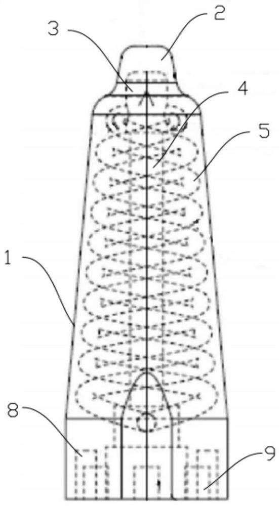
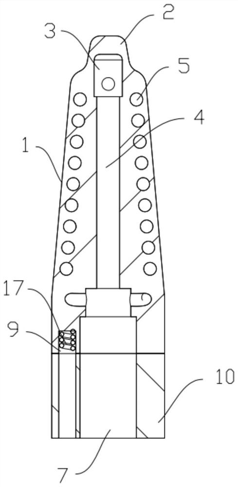
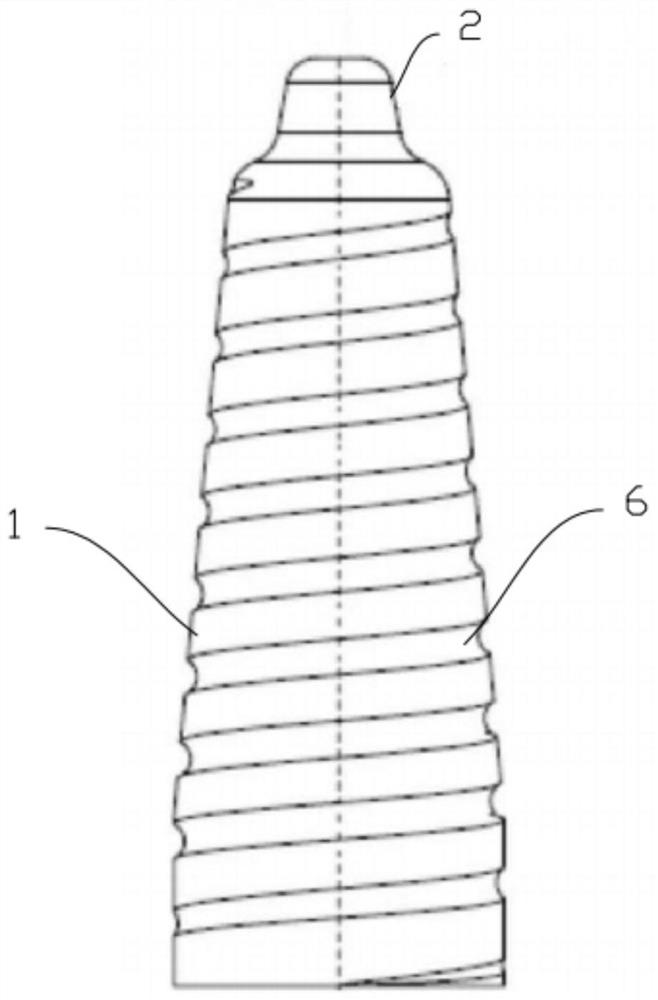
The invention relates to the technical field of machining, and provides a cooling core and a die-casting die thereof. The cooling core is inserted into a die with a molded surface; comprising a core body, a cooling part is arranged at the top of the core body, and the shape of the cooling part is the same as that of the molded surface corresponding to the cooling part; a water inlet cavity and a water outlet cavity are formed in the core body; a cooling cavity is formed in the cooling part and communicates with the water inlet cavity and the water outlet cavity. The cooling efficiency can be improved, the failure rate is reduced, and the quality is improved.

Description

technical field [0001] The invention relates to the technical field of processing, in particular to a cooling core and a die-casting mold thereof. Background technique [0002] The design of the cooling system of the die-casting die for the engine block is very critical to the product forming. Its main purpose is to take the heat away from the molten metal through direct heat conduction, to achieve the control of the modulus temperature, and through directional cooling, The part where the wall thickness is cooled as soon as possible is also the part where more heat is accumulated. [0003] The existing die-casting mold has a simple structure and has the following shortcomings: [0004] 1. For the thin-walled part of the mold, local cooling can play a direct role, but for the thick-walled part of the mold, that is, the part with more heat accumulation, the heat taken away is limited at this time, causing the temperature of this part to be too high. The cooling effect is not...

Claims


Application Information

Patent Timeline
Patent Type & Authority Applications(China)
IPC IPC(8): B22D17/22
CPCB22D17/22
Inventor 邓纮黄嘉铭陈华登刘剑彬胡亮
Owner GUANGQI HONDA
Learn More