3D printing mold cooling method and system

A mold cooling and 3D printing technology, applied in the field of 3D printing, can solve problems such as affecting the quality of material molding

Pending Publication Date: 2022-07-29
昆山优联模具科技有限公司
7 Cites 0 Cited by

AI-Extracted Technical Summary

Problems solved by technology

In addition, if the cooling temperature is too low,...

Method used

In some embodiments, the processing device can fit the temperature of the target printing area in the multiple printings of the history with the temperature of the target printing area by the least square method, and establish a fitting curve, based on the target in the multiple printings of the history The temperature of the printing area calculates the temperature of the target printing area. In some embodiments, the processing device may also record the history fitting process, and correct the calculated temperature of the target printing area through the history fitting process, so as to obtain a better fitting effect.
Through the 3D printing mold cooling method described in some embodiments of this specification, it is possible to achieve targeted cooling based on the structure of the printed part and the temperature distribution, and to avoid incomplete cooling; in addition, for the printed part with a hollow structure, in Under the premise of ensuring the integrity of the structure, deep internal cooling makes the cooling process more uniform.
Through the process of adjusting the parameters of the 3D printer described in some embodiments of this manual, the cooling efficiency can be improved under the premise of ensuring the printing quality, and for the noise generated by the rotation of the cooling fan, the printing parameters can be adjusted according to the actual noise situation and the noise threshold can be corrected , which can reduce noise and improve user experience while maintaining normal printing.
[0045] Some embodiments of this specification use real-time temperature distribution data to determine the temperature information of different positions in the printed matter, so that the real-time temperature-space correspondence of the printer can be obtained, which helps to improve the accuracy of the cooling process.
[0059] The second tuyere may be a tuyere used to dissipate heat from printed materials. For example, the second tuyere may be a tuyere used to cool materials in other locations that have been printed in the print. During the printin...

Abstract

The embodiment of the invention provides a cooling method for a 3D printing mold. The cooling method is used for a 3D printer comprising a cooling air opening. The method comprises the following steps: acquiring environment parameters of a printed piece, wherein the environment parameters comprise temperature information; and based on the environment parameters, the rotating speed of a cooling fan in the 3D printer is adjusted so as to control the flow of cooling air in the cooling air opening.

Application Domain

Additive manufacturing apparatus

Technology Topic

Process engineeringComputer printing +4

Image

  • 3D printing mold cooling method and system
  • 3D printing mold cooling method and system
  • 3D printing mold cooling method and system

Examples

  • Experimental program(1)

Example Embodiment

[0014] In order to illustrate the technical solutions of the embodiments of the present specification more clearly, the following briefly introduces the accompanying drawings that are used in the description of the embodiments. Obviously, the accompanying drawings in the following description are only some examples or embodiments of the present specification. For those of ordinary skill in the art, the present specification can also be applied to the present specification according to these drawings without any creative effort. other similar situations. Unless obvious from the locale or otherwise specified, the same reference numbers in the figures represent the same structure or operation.
[0015] It should be understood that "system", "device", "unit" and/or "module" as used herein is a method used to distinguish different components, elements, parts, sections or assemblies at different levels. However, other words may be replaced by other expressions if they serve the same purpose.
[0016] As shown in this specification and claims, unless the context clearly dictates otherwise, the words "a", "an", "an" and/or "the" are not intended to be specific in the singular and may include the plural. Generally speaking, the terms "comprising" and "comprising" only imply that the clearly identified steps and elements are included, and these steps and elements do not constitute an exclusive list, and the method or apparatus may also include other steps or elements.
[0017] Flowcharts are used in this specification to illustrate operations performed by a system according to an embodiment of this specification. It should be understood that the preceding or following operations are not necessarily performed in the exact order. Instead, the various steps can be processed in reverse order or simultaneously. At the same time, other actions can be added to these procedures, or a step or steps can be removed from these procedures.
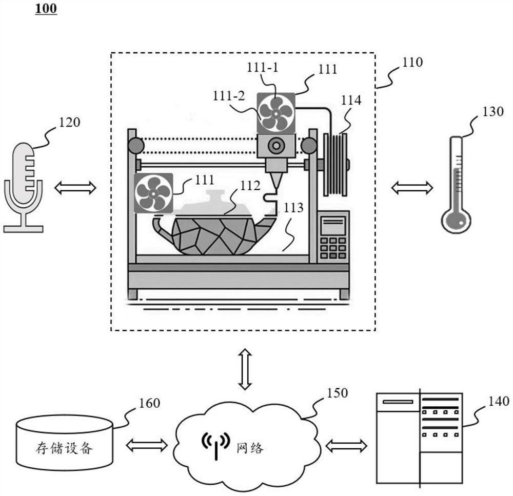
[0018] figure 1 It is a schematic diagram of the application scenario of the 3D printing mold cooling system according to some embodiments of this specification.
[0019] like figure 1 As shown, the application scenario 100 of the 3D printing mold cooling system may include a 3D printing device 110, a noise detection device 120, a temperature detection device 130, a processing device 140, a network 150 and a storage device 160. The 3D printing mold cooling system can be used in 3D printing. Intelligent and precise cooling during printing.
[0020] The 3D printing apparatus 110 may be used to print 3D objects (prints). The 3D printing apparatus 110 also includes, but is not limited to, a cooling device 111 , a printed part 112 , a printing area 113 , and a printing material 114 and the like. For example, the 3D printing device 110 can receive the printing instruction sent by the processing device 140 to perform 3D printing work; in some embodiments, the 3D printing device 110 can obtain the data output by the cooling device 111 and input the data to the processing device 140 . In some embodiments, the 3D printing device is also referred to as a 3D printer.
[0021] The cooling device 111 can be used to reduce the temperature of the printing environment, the temperature of the printing equipment, and the temperature of the printing material. For example, the cooling device may include a cooling fan 111-1, a tuyere (air outlet) 111-2, and the like. In some embodiments, the cooling device 111 may be used to cool the print 112 , the print area 113 , the print material 114 , and the like. In some embodiments, the rotational speed of the cooling fan 111-1 can be adjusted so as to control the flow rate of the cooling air from the air outlet (air outlet) 111-2.
[0022] A noise detection device 120 (also known as a noise detector) may be used to detect noise data. For example, the noise detection device 120 may include a noise detector, a sound level meter, a decibel meter, a noise spectrum analyzer, and other devices. In some embodiments, the noise detection device 120 may detect noise information emitted by the 3D printing device 110 .
[0023] The temperature detection device 130 may be used to detect temperature data. For example, the temperature detection device 130 may include devices such as a thermometer, a temperature sensor, a thermal resistance, a thermocouple, and the like. In some embodiments, the temperature detection device 130 may detect temperature information of the print 112 , the print area 113 , and the print material 114 .
[0024] Processing device 140 may process data and/or information from at least one component of the present system or an external data source. For example, the processing device 140 may acquire printing information output by the 3D printing device 110 . In some embodiments, processing device 140 may be local or remote. For example, the processing device 140 may acquire environmental information and/or data from the storage device 160, the noise detection device 120, the temperature detection device 130 and the cooling device 111 in a wired or wireless manner, and adjust the fan 111 in the cooling device 111 according to the environmental information The rotation speed of -1 is used to control the flow rate of cooling air in the air outlet 111-2 in the cooling device 111. In some embodiments, processing device 140 may be implemented on a cloud platform.
[0025] The network 150 may connect various components of the system and/or connect portions of the system with external resources. The network 150 enables communication between the various components, as well as with other components outside the system. For example, the processing device 140 obtains information and/or instructions from the storage device 160 , the noise detection device 120 , the temperature detection device 130 , and the cooling device 111 via the network 150 .
[0026] Storage device 160 may be used to store data and/or instructions. For example, storage device 160 may store instructions issued by processing device 140 . For another example, the storage device 160 may store the noise detection apparatus 120 and the acquired noise information. For another example, the storage device 160 may store the temperature information acquired by the temperature detection apparatus 130 . For another example, the storage device 160 may store the cooling information output by the cooling device 111 . In some embodiments, the storage device 160 may store the fan speed output by the cooling device. The storage device 160 may include one or more storage components, and each storage component may be an independent device or a part of other devices. In some embodiments, the storage device 160 may be implemented on a cloud platform.
[0027] It should be noted that application scenario 100 is provided for illustrative purposes only, and is not intended to limit the scope of this application. For those skilled in the art, various modifications or changes can be made based on the description of this specification. For example, the application scenario 100 may also include information sources. However, such changes and modifications do not depart from the scope of this application.
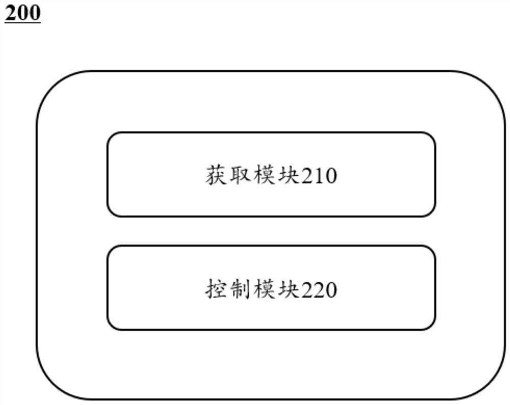
[0028] figure 2 It is a system diagram of a 3D printing mold cooling system 200 according to some embodiments of the present specification.
[0029] like figure 2 As shown, the 3D printing mold cooling system may include an acquisition module 210 and a control module 220 .
[0030] The acquiring module 210 is configured to acquire environmental parameters of the print; the environmental parameters include temperature information. For the environmental parameters of the print and how to obtain it, see image 3 and related descriptions thereof, which will not be repeated here.
[0031] The control module 220 is configured to adjust the rotation speed of the cooling fan in the 3D printer based on the environmental parameter, so as to control the flow rate of the cooling air in the cooling tuyere. For the rotational speed of the cooling fan, the flow rate of the cooling air and how to adjust and/or control it, see image 3 and related descriptions thereof, which will not be repeated here.
[0032] It should be noted that the above description of the system and its components is only for the convenience of description, and does not limit the description to the scope of the illustrated embodiments. It can be understood that for those skilled in the art, after understanding the principle of the system, it is possible to arbitrarily combine the various components, or form a subsystem to connect with other components without departing from the principle. For example, each component may share one storage device, and each component may also have its own storage device. Such deformations are all within the protection scope of this specification.
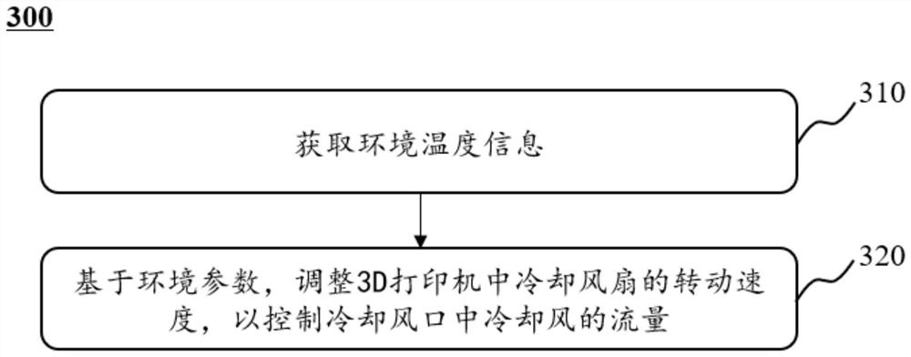
[0033] image 3 This is an exemplary flow chart of a method for cooling a 3D printing mold according to some embodiments of the present specification. like image 3 As shown, the process 300 includes the following steps. In some embodiments, process 300 may be performed by a processing device.
[0034]In some embodiments, the 3D printer may include a cooling tuyere (cooling device), and the cooling tuyere may further include a cooling fan. In response to the processing device controlling the cooling device to start, the cooling fan rotates to generate air flow at the cooling tuyere, and through the air flow, the heat of the printed parts, nozzles and other components is taken away to achieve heat dissipation in the 3D printing process. In some embodiments, the 3D printer may be supplemented with components such as a noise detection device, a temperature detection device, etc., for obtaining parameters related to the printing process and the cooling process, and the functions of each component can be described later.
[0035] Step 310: Obtain environmental parameters of the print; the environmental parameters include temperature information. In some embodiments, step 310 may be performed by acquisition module 210 .
[0036] The printed part can be the target part to be printed by the 3D printing part, including the target part in printing and the target part after printing. The printed part may be a target part composed of metal material, resin material, plastic material, and the like.
[0037] The environmental parameter may be a parameter related to the environment in which the print is located, for example, the environmental parameter may include temperature information, noise information, cooling information, and the like.
[0038] In some embodiments, the environmental parameters may be acquired by an acquisition module or a component thereof. For example, temperature information and the like are acquired through a temperature detection device.
[0039] In some embodiments, the processing device may acquire the temperature information in the environmental parameters of the print based on the following methods, such as acquiring real-time temperature distribution data of different angles of the print based on an infrared camera, and determining the temperature distribution based on the real-time temperature distribution data. temperature information at various locations in the printout.
[0040] The infrared camera may be a device for acquiring the relationship between temperature and its corresponding position. For example, the infrared camera may be a thermal imager, a thermal imaging camera, a thermal imaging detector, or the like. In some embodiments, the infrared camera is movable. For example, movement based on preset paths, or movement through slide rails, etc. In some embodiments, the motion of the infrared camera may include up and down motion, left and right motion, and the like.
[0041] The real-time temperature distribution data may be real-time temperature distribution data at different positions of the print. In the 3D printing process, different positions of the printed part are not printed at the same time, so there is a temperature difference due to the printing sequence. The real-time temperature distribution data can reflect the specific temperature distribution of different positions of the printed part due to the printing time.
[0042] In some embodiments, the real-time temperature distribution data may differentiate the temperature or temperature range of different regions based on the colors of the different regions in the images captured by the infrared camera. For example, warm colors such as red indicate relatively high temperatures, and cool colors such as blue indicate relatively low temperatures.
[0043] In some embodiments, the size of the area corresponding to different colors reflects the area occupied by the temperature corresponding to the color in the printed part. For example, a certain color occupies an area of ​​50cm in the image 2 , then the area corresponding to the temperature of the color occupies an area of ​​50cm 2.
[0044] In some embodiments, the processing device may process an image captured by an infrared camera. One or more pixels in the image correspond to different positions in the printing area. Based on the color of the pixel, the temperature of the printing area may be determined. For example, if the coordinates of a pixel point are (100, 300), which corresponds to the position of the printing area (100, 300), and the temperature data corresponding to the color of the position in the infrared image is 85°C, it can be determined that the temperature of this position in the printing area is 85°C.
[0045] In some embodiments of the present specification, the temperature information of different positions in the printed part can be determined by using the real-time temperature distribution data, and the real-time temperature-spatial correspondence of the printer can be obtained, which is helpful to improve the accuracy of the cooling process.
[0046] In some embodiments, the processing device may determine temperature information for different locations in the print based on real-time temperature profile data.
[0047] The temperature information may be temperature data of the print. For example, the temperature information may be the temperature in Fahrenheit (°F), the temperature in Celsius (°C), etc. of the print.
[0048] In some embodiments, different positions of the print may correspond to temperature information of different positions respectively. For example, if a certain print is printed from the bottom up, the lower part and the upper part of the printed part respectively correspond to different temperature information.
[0049] In some embodiments, the processing device may use a certain position of the print as the target position, and fuse the temperature distribution within a preset range of the target position to determine the temperature of the target position.
[0050] The fusion may be to calculate the average or weighted average of temperature distributions within a preset range of the target position, wherein the weight may be determined by the distance between the target position and other points within the preset range. For example, the preset range can be a circle (the radius can be 0.5cm, 1cm or 3cm, etc.), the circle takes the target position as the center, and the temperature of several points in the circle can be determined by the aforementioned temperature acquisition method. , the closer to the center of the circle, the greater the weight coefficient of the corresponding temperature, and the temperature of the target position can be obtained by weighted average of the temperature values ​​of each point.
[0051] In some embodiments, when acquiring the real-time temperature distribution data of the print at different angles based on the infrared camera, the processing device may acquire the print parameters of the print, and determine whether the print satisfies the preset conditions based on the print parameters. If the piece meets the preset conditions, the infrared camera is controlled to penetrate deep into the print piece to obtain the temperature distribution inside the print piece. For example, if it is determined based on the printing parameters that there is a large cavity (eg, having an inner cavity) inside the print, the infrared camera can be controlled to penetrate deep into the print to obtain the temperature distribution inside the print.
[0052] The print parameters can be any parameters related to the printing process. For example, the printing parameters may include the moving speed of the nozzle, the printing speed, the appearance size of the printed part, the size and size of the hollow part, the thickness, the area of ​​the cavity, the slicing parameters, and the like. In some embodiments, print parameters may be set by the printer system, or determined by user input of print data.
[0053] The preset condition may be a precondition for judging whether to control the infrared camera to penetrate deep into the print. For example, the preset conditions may include that the print is hollow, the area of ​​the hollow/void of the print is greater than a preset threshold, and the like.
[0054] Step 320 , based on the environmental parameters, adjust the rotation speed of the cooling fan in the 3D printer to control the flow rate of the cooling air in the cooling tuyere. In some embodiments, step 320 may be performed by a control module.
[0055] The cooling process is an important process that needs to be accurately controlled in the 3D printing process. If the cooling speed is too slow, it may cause the material of the lower layer of printed parts to melt during the printing process; if the cooling temperature is too low or the cooling speed is too fast, it may lead to the upper and lower layers of printing. The material cannot be fused in time and delamination occurs. Therefore, it is necessary to control the flow of cooling air in the cooling tuyere to achieve the purpose of controlling the cooling process.
[0056] In some embodiments, the control device may adjust the rotational speed of the cooling fan in the 3D printer based on environmental parameters to control the flow of cooling air in the cooling tuyere. For example, when the temperature in the environment is high, the control device can increase the rotation speed of the cooling fan to generate a larger cooling air flow to achieve the purpose of heat dissipation.
[0057] In some embodiments, the 3D printer may include a plurality of cooling tuyere, each of which corresponds to at least one cooling fan; the cooling tuyere includes a first tuyere and a second tuyere.
[0058] The first tuyere may be a tuyere for cooling the printing material ejected by the nozzle of the 3D printer. For example, the first tuyere may be an tuyere that moves together with the nozzle and is used to cool the material ejected from the nozzle in real time in the print. During the printing process, the nozzle is usually heated to a certain temperature. If there is no good heat dissipation, the heat of the nozzle will be transferred to the throat and motor above, resulting in overheating and affecting the transfer of printing materials. The first air outlet for the heat dissipation of the printing material can ensure the smooth progress of printing. In some embodiments, the first tuyere may be automatically activated when the nozzle is heated or after the nozzle temperature reaches a temperature threshold.
[0059] The second tuyere may be an tuyere for dissipating heat from the printed printing material, for example, the second tuyere may be an tuyere for cooling materials in other locations that have been printed in the print. During the printing process, the printed material needs to continue to dissipate heat, so that it can be cured as soon as possible and reduce the deformation during the curing process. Therefore, setting a second air outlet to dissipate heat from the printed material can improve the printing efficiency. quality. In some embodiments, the second tuyere may be automatically activated at the beginning of the printing process.
[0060] In some embodiments of this specification, the descriptions of the first tuyere and the second tuyere are intended to illustrate, but do not mean to limit their functions, and their functions can be interchanged. For example, the first tuyere may be an tuyere for radiating heat from the printed printing material, and the second tuyere may be a tuyere for radiating heat from the printing material ejected from the nozzle of the 3D printer, or the like. In some embodiments, in addition to timely cooling the temperature of the material just ejected from the nozzle, the cooling system may also set multiple other air vents to cool other locations to ensure that the printed part and other components of the cooling system are fully cooled, for example, the cooling system Other air vents, such as third air vents, fourth air vents, etc., may also be included to dissipate heat from other components of the cooling system.
[0061] In some embodiments, the processing device may determine the rotational speed of the cooling fan corresponding to the first air outlet and the rotational speed of the cooling fan corresponding to the second air outlet based on temperature information at different positions of the print. For example, there is a preset correspondence between the temperature and the flow rate of the first tuyere and the flow rate of the second tuyere (that is, the rotation speed of the cooling fan corresponding to the first tuyere and the rotation speed of the cooling fan corresponding to the second tuyere). Determine the rotation speed of the cooling fan corresponding to the first tuyere and the rotation speed of the cooling fan corresponding to the second tuyere.
[0062] In some embodiments, the temperature is positively correlated with the rotation speed of the cooling fan corresponding to the first tuyere and the rotation speed of the cooling fan corresponding to the second tuyere, that is, the higher the temperature, the higher the rotation speed of the cooling fan corresponding to the first tuyere and the The rotation speed of the cooling fan corresponding to the second air outlet is higher.
[0063] In some embodiments, the processing device may acquire printing parameters of the print, and if the print meets a preset condition, control the second air outlet to penetrate deep into the print for cooling. The preset conditions may include that the printed part is hollow, the area of ​​the hollow/void of the printed part is greater than a preset threshold, and the like.
[0064] In some embodiments, the processing device may further determine whether to penetrate deep into the print for cooling and determine the location of the penetration based on the temperature distribution determined by the infrared camera. For example, when the processing device judges that the cavity area can accommodate the second air vent, the second air vent goes deep into the printer for cooling; when the processing device judges that the cavity content is simple in structure and the cavity is deep, it goes into a deeper position accordingly.
[0065] Through the 3D printing mold cooling method described in some embodiments of this specification, targeted cooling based on the structure and temperature distribution of the printed part can be realized to avoid incomplete cooling; in addition, for the printed part with a hollow structure, it is necessary to ensure the integrity of the structure. Under the premise of deep internal cooling, the cooling process is more uniform.
[0066] It should be noted that the above description about the process 300 is only for example and illustration, and does not limit the scope of application of this specification. For those skilled in the art, various modifications and changes can be made to the process 300 under the guidance of this specification. However, these corrections and changes are still within the scope of this specification. For example, process 300 may also include preprocessing steps.
[0067] Figure 4It is an exemplary schematic diagram of adjusting the parameters of the 3D printer based on the prediction results according to some embodiments of the present specification. Process 400 such as Figure 4 shown. In some embodiments, process 400 may be implemented by a processing device and components thereof.
[0068] Step 410: Acquire the temperatures of multiple print areas of the print. In some embodiments, step 410 may be performed by an acquisition module.
[0069] A print area can be a certain print location of a print. For example, the print area may be a certain coordinate position such as (30, 60, 80), or a set of multiple coordinate positions.
[0070] In some embodiments, the processing device may predict the temperature of the target print area based on the temperature of the target print area over the historical multiple prints.
[0071] The target printing area refers to the printing area whose temperature needs to be predicted, and any of the foregoing printing areas can be used as the target printing area.
[0072] In some embodiments, the processing device can predict the temperature of the target printing area based on various methods. For example, predicting the temperature of the target printing area can be realized by a prediction model. For the specific description of the prediction process, see Figure 5 and related descriptions.
[0073] In some embodiments, the processing device may predict the temperature of the target printing area by means of fitting based on the temperature of the target printing area in historical multiple printings.
[0074] In some embodiments, the processing device can use the least squares method to fit the temperature of the target printing area in the historical multiple printings with the temperature of the target printing area, and establish a fitting curve, based on the historical multiple printings. Temperature Calculates the temperature of the target print area. In some embodiments, the processing device may also record the history matching process, and correct the calculated temperature of the target printing area through the history matching process to obtain a better fitting effect.
[0075] Step 420: Determine the rotation speed of the cooling fan corresponding to the target printing area based on the temperature of the target printing area. In some embodiments, step 420 may be performed by a control module.
[0076] In some embodiments, there may be a preset correspondence between the temperature of the target printing area and the rotation speed of the cooling fan corresponding to the target printing area, and the rotation speed of the cooling fan corresponding to the target printing area may be determined based on the acquired temperature information. For example, the temperature is positively correlated with the rotation speed of the cooling fan, that is, the higher the temperature, the higher the rotation speed of the cooling fan.
[0077] In some embodiments, after acquiring the temperature data of the target printing area, the processing device may further perform the following operation steps:
[0078] Step 430: Determine whether the predicted temperature of the target printing area is greater than the preset temperature value, and if so, adjust the printing parameters. In some embodiments, step 430 may be performed by a control module.
[0079] The preset temperature value may be a maximum temperature for judging whether to adjust the printing parameters based on an empirical value setting. For example, the preset temperature value may be 150°C, 200°C, or the like.
[0080] In some embodiments, adjusting the printing parameters may include adjusting the speed of movement of the nozzle, eg, reducing the speed of movement of the nozzle. Adjusting the moving speed of the nozzle is adjusting the printing speed. When the temperature is too high and exceeds the temperature threshold, the processing device can reduce the printing speed to control the cooling process.
[0081] In the process of adjusting printing parameters described in some embodiments of this specification, the cooling process is controlled by controlling the printing speed, so as to avoid damage to the printer and the printed parts under extreme temperature conditions such as overheating.
[0082] In some embodiments, the magnitude of the adjustment in the speed of movement of the nozzle is related to the confidence of the prediction model.
[0083] The confidence level of the prediction model may be a parameter reflecting the confidence level of the prediction result. For example, the confidence level can be a number within 100 such as 95, 80, etc., or a percentage such as 95%, etc. In some embodiments, the confidence level of the prediction model can be determined manually, or determined based on the accuracy of historical prediction results.
[0084] In some embodiments, the higher the confidence, the greater the adjustment in the speed of movement of the nozzle. For example, the higher the confidence, the greater the drop in the speed of movement of the nozzle. For more information on predictive models and their confidence levels see Figure 5 description of.
[0085] In some embodiments of this specification, the confidence of the prediction model is introduced to determine the adjustment range of the nozzle moving speed, which reduces the interference of the model with poor prediction effect on the printing process.
[0086] Step 440 , based on the rotation speed of the cooling fan corresponding to the predicted temperature of the target printing area, determine whether the noise of the cooling fan is greater than a noise threshold, and if it is greater, adjust the printing parameters. In some embodiments, step 440 may be performed by a control module.
[0087] The noise threshold may be a noise maximum value based on an empirically determined determination of whether to adjust the printing parameters. For example, the noise threshold may be a specific decibel value such as 100 decibels and the like.
[0088] In some embodiments, the noise of the cooling fan may be determined by a noise detection device.
[0089] In some embodiments, adjusting the printing parameters may include: reducing the rotation speed of the cooling fan, reducing the moving speed of the nozzle and the spraying speed, etc., where the spraying speed may be the speed at which the nozzles spray the printing material during the printing process. By reducing the rotation speed of the cooling fan, the friction between the cooling fan blade and the air and the friction between the blade surface and the rotating shaft of the blade can be reduced, thereby reducing noise; by reducing the moving speed and spraying speed of the nozzle, it can be Slows down the printing speed, thereby reducing noise caused by the movement of the bracket connecting the nozzles.
[0090] In some embodiments, the magnitude of the print parameter adjustment is related to the relationship between the noise generated and the noise threshold. For example, when the noise decibel generated is much larger than the noise threshold, the range of the reduction in the moving speed of the nozzle can be appropriately increased to reduce the influence of the larger noise decibel.
[0091] In some embodiments, the processing device may modify the noise threshold based on actual conditions of the printer.
[0092] In some embodiments, the correction of the noise threshold includes: acquiring the noise corresponding to the actual rotation speed of the cooling fan and a preset noise threshold for correction. For example, the processing device can correct the noise threshold by the noise corresponding to the actual rotational speed of the cooling fan based on information such as the actual model of the printer, age of use, wear and tear status, cleaning conditions, and environmental conditions. If noise is generated, high-speed rotation may generate more noise. For such situations, the corresponding correction process for the printer can be to increase the noise threshold accordingly; for another example, when the printer is in a noise-sensitive application scenario (such as a laboratory), its corresponding The correction process can be to reduce the noise threshold accordingly.
[0093] Through the process of adjusting the parameters of the 3D printer described in some embodiments of this specification, the cooling efficiency can be improved on the premise of ensuring the printing quality, and for the noise generated by the rotation of the cooling fan, the printing parameters can be adjusted according to the actual noise situation and the noise threshold can be corrected. Reduce noise and improve user experience while maintaining normal printing.
[0094] It should be noted that the above description about the process 400 is only for example and illustration, and does not limit the scope of application of this specification. For those skilled in the art, various modifications and changes can be made to the process 400 under the guidance of this specification. However, these corrections and changes are still within the scope of this specification. For example, process 400 may also include preprocessing steps.
[0095] Figure 5 is an exemplary structural diagram of a prediction model according to some embodiments of the present specification. Structure 500 as Figure 5 shown.
[0096] The predictive model may be a model for predicting the temperature of the target print area. For example, the prediction model can be a sequence model like LSTM or RNN.
[0097] The input of the prediction model can include the temperature data of the target printing area, the temperature data of the adjacent area of ​​the target printing area, the distance between the adjacent area and the target printing area at multiple time points before the current time point, and the output can include a specific Predicted temperature of the target print area in cooling mode (eg at a certain fan speed). In some embodiments, the output of the predictive model may also include a confidence level for the predicted temperature of the target print area.
[0098] The adjacent area of ​​the target printing area may be an area within a preset range near the target printing area. For example, the adjacent area may be an area within 10 cm from the center of the target printing area, or the like.
[0099] In some embodiments, the predictive model may be trained from multiple labeled training samples. For example, multiple labeled training samples can be input into the initial prediction model, a loss function can be constructed from the labels and the results of the initial prediction model, and the parameters of the initial prediction model can be iteratively updated based on the loss function. When the loss function of the initial prediction model satisfies the preset conditions, the model training is completed, and a trained prediction model is obtained. The preset conditions may be that the loss function converges, the number of iterations reaches a threshold, and the like.
[0100] In some embodiments, the training samples may include at least multiple groups of historical printing data, and each group of historical printing data may include multiple temperature data of the target printing area in each historical printing, and temperatures of multiple adjacent areas of the historical target printing area. The distance between the data, historical proximity area and the target print area. The label can be the time required for the part to be cooled to cool to a specific temperature in a specific cooling mode, and the label can be obtained based on manual annotation. In some embodiments, the label may also be the temperature change curve of the to-be-cooled part of the target printing area predicted by the model in the next time period. Each point in the temperature curve represents the temperature of the part to be cooled at the corresponding time point.
[0101] In some embodiments, the prediction model structure may also be a structure obtained by combining an embedding layer and a sequence model.
[0102] The input of the prediction model can include printing material, nozzle temperature, nozzle moving speed, nozzle ejecting speed, cooling rotation speed, etc., and the output can include the predicted temperature of the target printing area.
[0103] The printing material can be various parameters of the material involved in the printing, for example, specific heat capacity, thermal conductivity, and the material of the printing material.
[0104] The embedding layer may be a model for extracting temperature feature vectors, for example, the embedding layer may be a convolutional neural network model or the like.
[0105] The input of the embedded layer can include printing material, nozzle temperature, nozzle moving speed, nozzle ejecting speed, cooling rotation speed, etc., and the output can include temperature feature vector.
[0106] The temperature feature vector may be a feature vector reflecting the influence of printing material, nozzle temperature, nozzle moving speed, nozzle ejecting speed, cooling rotation speed, etc. on temperature. The elements of the temperature feature vector may include the printing material, the nozzle temperature, the moving speed of the nozzle, the ejection speed of the nozzle, the rotational speed of the cooling, and the like.
[0107] The sequence model may be a model for obtaining the predicted temperature of the target printing area, for example, the sequence model may be an LSTM model or the like.
[0108] The input to the sequence model may include a temperature feature vector, and the output may include the predicted temperature of the target print area.
[0109] In some embodiments, the output of the embedding layer may be the input of the sequence model, and the embedding layer and the sequence model may be obtained by joint training. For example, input training sample data to the embedding layer, that is, historical sample data of printing material, nozzle temperature, nozzle moving speed, nozzle spraying speed, cooling rotation speed, etc., to obtain the temperature feature vector output by the embedding layer; The feature vector is used as the training sample data, input the sequence model to obtain the predicted temperature of the target printing area, and use the predicted temperature of the sample target printing area to verify the output of the sequence model; using the back-propagation characteristics of the neural network model, the output of the embedding layer is obtained. The verification data of the temperature feature vector is used as the label to train the embedding layer, wherein the label can be obtained by manual annotation. When the loss functions of the embedding layer and sequence model meet the preset conditions, the training is completed, and the trained embedding layer and sequence model are obtained. The preset conditions may be that the loss function converges, the number of iterations reaches a threshold, and the like.
[0110] In some embodiments, the embedding layer can also be jointly trained with a custom model. A custom model can be the model used to train the embedding layer. Custom models can include embedding layers and output layers.
[0111] Inputs to a custom model can include printing material, nozzle temperature, nozzle moving speed, nozzle ejecting speed, cooling rotation speed, etc., and output can include predicted temperature sequences.
[0112] The input of the embedded layer in the custom model can include printing material, nozzle temperature, nozzle moving speed, nozzle ejecting speed, cooling rotation speed, etc. The output can include temperature feature vector; the input of the output layer in the custom model The temperature feature vector (ie the output of the embedding layer) can be included, and the output can include the predicted temperature sequence.
[0113] The training sample data in the joint training process of the embedding layer and the output layer in the custom model can include historical sample data such as printing material, nozzle temperature, nozzle moving speed, nozzle spraying speed, cooling rotation speed, etc. The training label can be Historical temperature series. For a specific description of the custom model training process, see the above description of the joint training of the embedding layer and the sequence model.
[0114] In some embodiments of the present specification, a process of determining a predicted temperature based on various printing parameters can be implemented through a prediction model. The embedding layer is introduced into the prediction process, which can pre-determine the temperature change relationship and its reasonable range, so as to avoid the unrealistic model output results; the model training can use the embedding layer-sequence model joint training or the embedding layer-custom model joint training, which can reduce the number of samples , to avoid the problem that the temperature feature vector is difficult to determine as a label when the embedding layer is trained separately.
[0115] Image 6 It is an exemplary schematic diagram of adjusting the rotation speed based on noise information according to some embodiments of the present specification. like Image 6 As shown, the process 600 includes the following steps. In some embodiments, process 600 may be performed by a processing device.
[0116] In some embodiments, the processing device may obtain noise information of the print space based on the noise detector.
[0117] A noise detector may be a device for detecting the presence and intensity of noise. For example, the noise detector can be a handheld sound level meter, a decibel meter, a noise spectrum analyzer, etc.
[0118] The noise information may be noise-related information. For example, the noise information may include noise decibel size, noise frequency, noise source and other information.
[0119] The printing space can be the space in which the 3D printer and the print are located during the printing process. For example, in laboratories, factories, classrooms and other spaces, for example, processing equipment can obtain the noise information of the printing laboratory during 3D printing based on the decibel meter as the noise information of the printing space.
[0120] In some embodiments, the processing device may adjust the rotational speed of the fan based on the noise information. For example, when the decibel level of the noise is greater than a preset noise threshold, the processing device controls the rotation speed of the cooling fan to decrease.
[0121] In some embodiments, when the decibel level of the noise is greater than a preset noise threshold, the processing device controls to reduce the rotation speed of the cooling fan corresponding to the second air outlet or turn off part of the cooling fan corresponding to the second air outlet.
[0122] In some embodiments, the system may include a plurality of second air vents, each of which may include a plurality of cooling fans. In some embodiments, reducing the rotation speed of the cooling fan corresponding to the second air outlet may be to reduce the cooling fan corresponding to the second air outlet corresponding to the second air outlet in the printing area where the actual detected temperature or the predicted temperature of the plurality of second air outlets is lower than the temperature threshold rotation speed. For example, when the noise exceeds the noise threshold and it is necessary to reduce the rotation speed of the cooling fan corresponding to the second air outlet, the rotation speed of the cooling fan of the second air outlet corresponding to the lower temperature printing area can be preferentially reduced to ensure other high temperature areas. cooling effect.
[0123] In some embodiments, turning off part of the cooling fans may be turning off the cooling fans corresponding to the second tuyere corresponding to the printing area where the actual detected temperature or the predicted temperature of the plurality of second tuyere is less than the temperature threshold. For example, when the noise exceeds the noise threshold and the cooling fan corresponding to the second air outlet needs to be turned off, the cooling fan of the second air outlet corresponding to the lower temperature printing area can be turned off preferentially to ensure the cooling effect of other high temperature areas. In some embodiments, the temperature distribution of the printing area can be determined by real-time temperature distribution data, see image 3 and related descriptions.
[0124] Through the process of adjusting the rotation speed based on noise information described in some embodiments of this specification, on the premise of ensuring the cooling effect, the cooling fan corresponding to the area that does not require cooling or has a low cooling demand can be decelerated or turned off, reducing power consumption. At the same time reduce noise and improve user experience.
[0125] It should be noted that the above description about the process 600 is only for example and illustration, and does not limit the scope of application of this specification. For those skilled in the art, various modifications and changes can be made to the process 600 under the guidance of this specification. However, these corrections and changes are still within the scope of this specification. For example, process 600 may also include preprocessing steps.
[0126] Some embodiments of this specification also disclose a computer-readable storage medium, the storage medium stores computer instructions, and after the computer reads the computer instructions in the storage medium, the computer executes the above-mentioned 3D printing mold cooling method.
[0127] The basic concept has been described above. Obviously, for those skilled in the art, the above detailed disclosure is only an example, and does not constitute a limitation of the present specification. Although not explicitly described herein, various modifications, improvements, and corrections to this specification may occur to those skilled in the art. Such modifications, improvements, and corrections are suggested in this specification, so such modifications, improvements, and corrections still belong to the spirit and scope of the exemplary embodiments of this specification.
[0128] Meanwhile, the present specification uses specific words to describe the embodiments of the present specification. Examples such as "one embodiment," "an embodiment," and/or "some embodiments" mean a certain feature, structure, or characteristic associated with at least one embodiment of this specification. Therefore, it should be emphasized and noted that two or more references to "an embodiment" or "one embodiment" or "an alternative embodiment" in various places in this specification are not necessarily referring to the same embodiment . Furthermore, certain features, structures or characteristics of the one or more embodiments of this specification may be combined as appropriate.
[0129] Furthermore, unless explicitly stated in the claims, the order of processing elements and sequences described in this specification, the use of alphanumerics, or the use of other names is not intended to limit the order of the processes and methods of this specification. While the foregoing disclosure discusses by way of various examples some embodiments of the invention presently believed to be useful, it is to be understood that such details are for purposes of illustration only and that the appended claims are not limited to the disclosed embodiments, but rather The requirements are intended to cover all modifications and equivalent combinations that fall within the spirit and scope of the embodiments of this specification. For example, although the system components described above may be implemented by hardware devices, they may also be implemented by software-only solutions, such as installing the described systems on existing servers or mobile devices.
[0130] Similarly, it should be noted that, in order to simplify the expressions disclosed in this specification and thus help the understanding of one or more embodiments of the invention, in the foregoing description of the embodiments of this specification, various features may sometimes be combined into one embodiment, in the drawings or descriptions thereof. However, this method of disclosure does not imply that the subject matter of the description requires more features than are recited in the claims. Indeed, there are fewer features of an embodiment than all of the features of a single embodiment disclosed above.
[0131] Some examples use numbers to describe quantities of ingredients and attributes, it should be understood that such numbers used to describe the examples, in some examples, use the modifiers "about", "approximately" or "substantially" to retouch. Unless stated otherwise, "about", "approximately" or "substantially" means that a variation of ±20% is allowed for the stated number. Accordingly, in some embodiments, the numerical parameters set forth in the specification and claims are approximations that can vary depending upon the desired characteristics of individual embodiments. In some embodiments, the numerical parameters should take into account the specified significant digits and use a general digit reservation method. Notwithstanding that the numerical fields and parameters used in some embodiments of this specification to identify the breadth of their ranges are approximations, in specific embodiments such numerical values ​​are set as precisely as practicable.
[0132] For each patent, patent application, patent application publication, and other material, such as article, book, specification, publication, document, etc., cited in this specification, the entire contents of which are hereby incorporated by reference into this specification are hereby incorporated by reference. Application history documents that are inconsistent with or conflict with the contents of this specification are excluded, as are documents (currently or hereafter appended to this specification) limiting the broadest scope of the claims of this specification. It should be noted that, if there is any inconsistency or conflict between the descriptions, definitions, and/or usage of terms in the accompanying materials of this specification and the contents of this specification, the descriptions, definitions and/or usage of terms in this specification shall prevail .
[0133] Finally, it should be understood that the embodiments described in this specification are only used to illustrate the principles of the embodiments of this specification. Other variations are also possible within the scope of this specification. Accordingly, by way of example and not limitation, alternative configurations of the embodiments of this specification may be considered consistent with the teachings of this specification. Accordingly, the embodiments of this specification are not limited to those expressly introduced and described in this specification.

PUM

no PUM

Description & Claims & Application Information

We can also present the details of the Description, Claims and Application information to help users get a comprehensive understanding of the technical details of the patent, such as background art, summary of invention, brief description of drawings, description of embodiments, and other original content. On the other hand, users can also determine the specific scope of protection of the technology through the list of claims; as well as understand the changes in the life cycle of the technology with the presentation of the patent timeline. Login to view more.
Why Eureka
Try Eureka