Glass plate pushing mechanism

A technology of pushing mechanism and glass plate, applied in glass manufacturing equipment, glass cutting device, conveyor objects, etc., can solve the problem of high personnel cost, achieve the effect of reducing cost, avoiding manual push, and improving efficiency

Pending Publication Date: 2022-07-29
河北光兴半导体技术有限公司 +1
View PDF14 Cites 0 Cited by
  • Summary
  • Abstract
  • Description
  • Claims
  • Application Information

AI Technical Summary

Problems solved by technology

[0002] At present, in the production process of the overflow glass production line, manual pushing is usually used. Manual pushing requires at least 2 people per shift, and 3 shifts push the boards 24 hours a day, resulting in high personnel costs.

Method used


Image

  • Glass plate pushing mechanism
  • Glass plate pushing mechanism
  • Glass plate pushing mechanism

Examples


Embodiment Construction

[0037] Exemplary embodiments of the present disclosure will be described in more detail below with reference to the accompanying drawings. While exemplary embodiments of the present disclosure are shown in the drawings, it should be understood that the present disclosure may be embodied in various forms and should not be limited by the embodiments set forth herein. Rather, these embodiments are provided so that the present disclosure will be more thoroughly understood, and will fully convey the scope of the present disclosure to those skilled in the art.

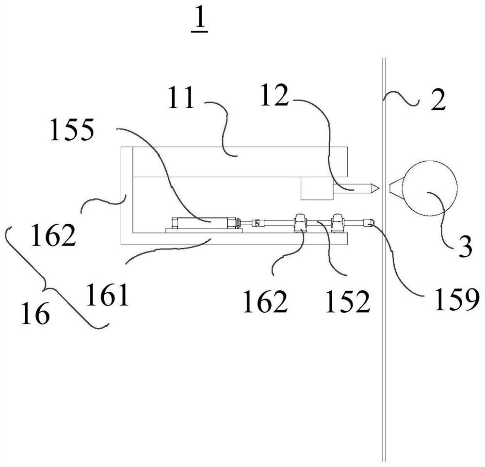
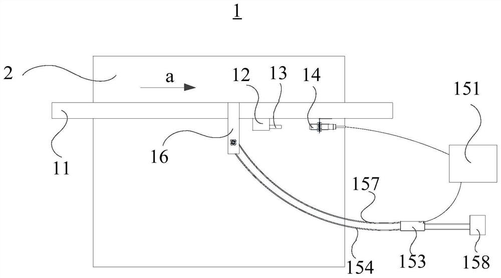
[0038] like figure 1 and figure 2 As shown, the present application provides a glass plate pushing mechanism 1, comprising:

[0039] a beam 11, the beam 11 is arranged opposite the glass plate 2;

[0040] A cutter 12, the cutter 12 is movably connected to the beam 11 along the first direction, and the cutter 12 is disposed toward the glass plate 2 to cut the glass plate 2 along the first direction, the A sensing block 1...


PUM


Abstract

The invention provides a glass plate pushing mechanism, and relates to the technical field of glass plate production. The invention provides a glass plate pushing mechanism, which comprises a cross beam, a pushing mechanism and a driving mechanism, and is characterized in that the cross beam is opposite to a glass plate; the cutting knife is movably connected to the cross beam in the first direction, the cutting knife is arranged towards the glass plate so as to cut the glass plate in the first direction, and an induction block is fixedly arranged on the cutting knife; the receiver is fixedly arranged on the cross beam and is in wireless connection with the induction block, and the distance between the receiver and the induction block is a first preset distance in the first direction, so that when the distance between the induction block and the receiver is a second preset distance, the receiver receives an induction signal of the induction block; the pushing device is movably connected to the cross beam in the direction towards or away from the glass plate, and the pushing device is connected with the receiver so as to move towards the glass plate when receiving the induction signal to push the glass plate.

Description

technical field [0001] The present application relates to the technical field of glass plate production, and in particular, to a glass plate pushing mechanism. Background technique [0002] At present, in the production process of the overflow method glass production line, the manual push plate is usually used, and the manual push plate requires at least 2 people per shift, and 3 shifts push the plate 24 hours a day, resulting in high personnel costs. [0003] Therefore, how to provide an automatic push plate device has become an urgent problem to be solved. SUMMARY OF THE INVENTION [0004] The purpose of the embodiments of the present application is to provide a glass plate pushing mechanism and a ventilation device. [0005] In order to solve the above-mentioned technical problems, the embodiments of the present application provide the following technical solutions: [0006] A first aspect of the present application provides a glass plate pushing mechanism, comprising...

Claims


Application Information

Patent Timeline
Patent Type & Authority Applications(China)
IPC IPC(8): C03B33/03C03B33/037B65G47/82B65G49/06
CPCC03B33/03C03B33/037B65G47/82B65G49/064
Inventor 赵列成胡恒广张文亮左志民甄喜葛亚辉
Owner 河北光兴半导体技术有限公司
Why Eureka
Try Eureka