
Drawing method of photonic crystal fiber and photonic crystal fiber

A technology of photonic crystal fiber and manufacturing method, applied in the direction of manufacturing tools, glass manufacturing equipment, etc., can solve the problems of insufficient stability and replaceability of PCF, achieve increased stability and replaceability, and good radial uniformity Effect

Pending Publication Date: 2022-07-29
HANS LASER TECH IND GRP CO LTD
View PDF0 Cites 0 Cited by
  • Summary
  • Abstract
  • Description
  • Claims
  • Application Information

AI Technical Summary

Problems solved by technology

[0005] The technical problem to be solved by the present invention is: provide a drawing method of photonic crystal fiber and photonic crystal fiber, solve the problem of insufficient stability and replaceability of PCF in the production process in the prior art

Method used


Image

  • Drawing method of photonic crystal fiber and photonic crystal fiber
  • Drawing method of photonic crystal fiber and photonic crystal fiber
  • Drawing method of photonic crystal fiber and photonic crystal fiber

Examples


Embodiment Construction

[0055] In order to make the objectives, technical solutions and advantages of the present invention clearer, the present invention will be described in further detail below with reference to the accompanying drawings and embodiments, wherein the same or similar reference numerals represent the same or similar elements or elements with the same or similar functions throughout. element. It should be understood that the specific embodiments described herein are only used to explain the present invention, but not to limit the present invention. In addition, the technical features involved in the various embodiments of the present invention described below can be combined with each other as long as they do not conflict with each other.

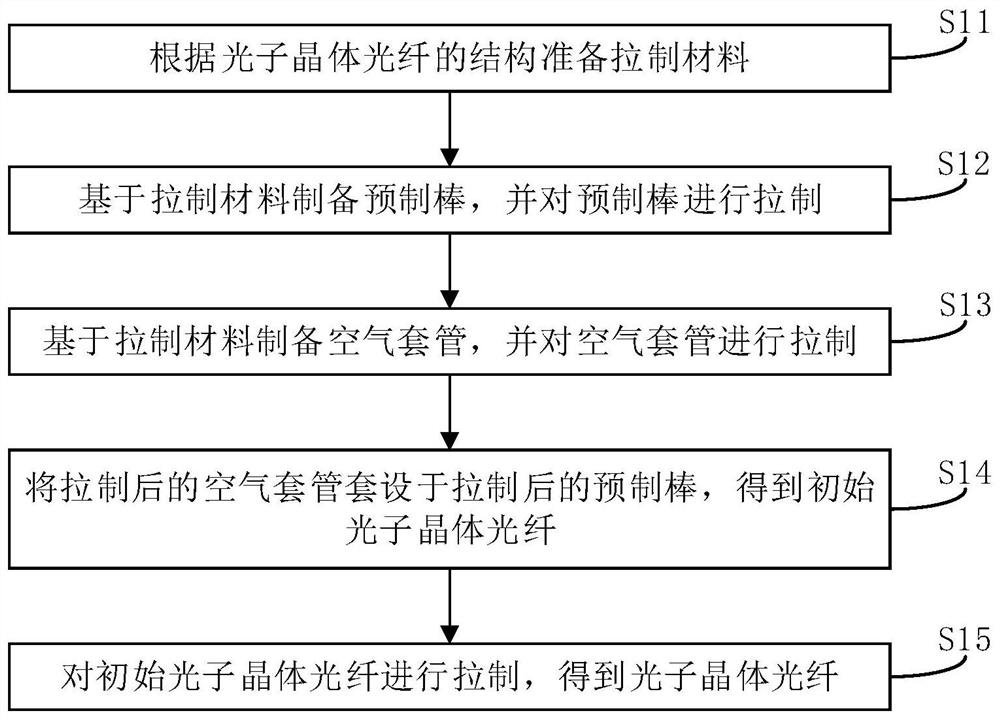
[0056] see figure 1 , figure 1 A schematic flowchart of a method for drawing a photonic crystal fiber provided by an embodiment of the present invention.

[0057] like figure 1 As shown, an embodiment of the present invention provides a method ...


PUM


Abstract

The invention provides a drawing method of a photonic crystal fiber and the photonic crystal fiber, and the drawing method of the photonic crystal fiber comprises the steps: preparing a drawing material according to the structure of the photonic crystal fiber; preparing a preform rod based on the drawing material, and drawing the preform rod; preparing the air sleeve based on the drawing material, and drawing the air sleeve; sleeving the drawn prefabricated rod with the drawn air sleeve to obtain an initial photonic crystal fiber; and drawing the initial photonic crystal fiber to obtain the photonic crystal fiber. According to the invention, the prefabricated rod and the air sleeve are drawn in stages, and then the drawn prefabricated rod and the air sleeve are subjected to combined drawing, so that various process parameters in the drawing process can be accurately controlled, the stability and replaceability of PCF in the production process are improved, and meanwhile, under the conditions of stable temperature, air pressure and drawing speed, the production efficiency is improved. And the radial uniformity of the drawn PCF is better.

Description

【Technical field】 [0001] The invention relates to the technical field of optical fiber drawing, in particular to a drawing method of a photonic crystal optical fiber and a photonic crystal optical fiber drawn by the drawing method of the photonic crystal optical fiber. 【Background technique】 [0002] Photonic Crystal Fibers (PCFs) are also known as Micro-Structured Fibers (MSFs). The cores of PCFs are composed of solid glass rods or hollow glass tubes, and the cladding is composed of regularly distributed air holes. constitute. PCF has more superior characteristics than traditional fibers in the field of gain fibers. Specifically, the microporous structure of PCF introduces air, so that the equivalent refractive index of the cladding is smaller than that of the core. The adjustment of the spacing can precisely control the refractive index difference between the cladding and the core; PCF can realize the non-cut-off single-mode transmission characteristics based on a large m...

Claims


Application Information

Patent Timeline
IPC IPC(8): C03B37/027
CPCC03B37/0279
Inventor 周芳屹杜明黄苏梅陈克胜李静庄宏洲谢祥强洪晓钦陆小松高云峰
Owner HANS LASER TECH IND GRP CO LTD
Learn More