Format grid vertex alignment method based on stitching relation and storage medium
A technology of grid vertices and first pattern, applied in CAD customization/personalization, instrumentation, design optimization/simulation, etc., can solve problems such as uneven grid vertices, inconsistent numbers, and difficult alignment of pattern grids, and achieve pattern The effect of uniform vertices, consistent number, and improved uniformity of the sheet mesh
- Summary
- Abstract
- Description
- Claims
- Application Information
AI Technical Summary
Problems solved by technology
Method used
Image

Examples
Embodiment 1
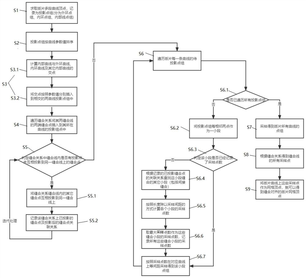
[0063] like Figure 1-11 A method for aligning pattern mesh vertices based on a stitching relationship shown in Embodiment 1 includes the following steps:
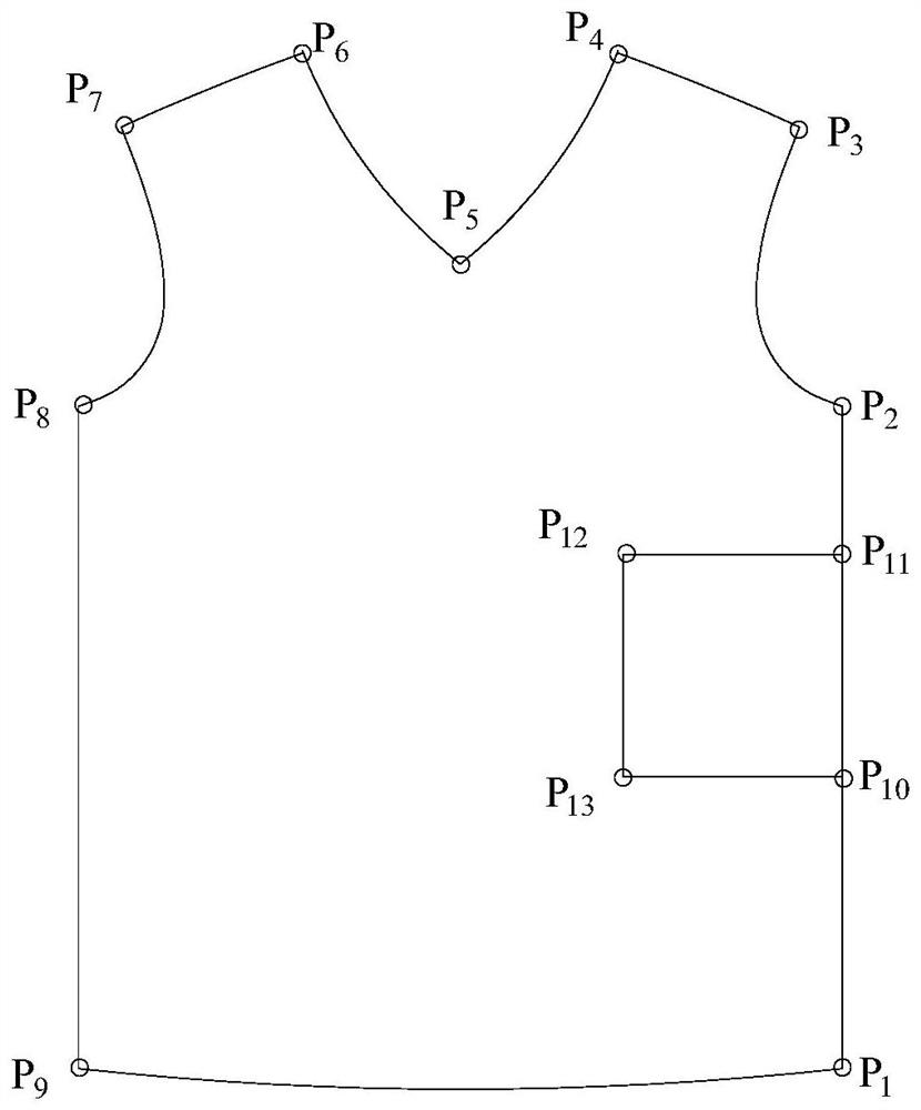
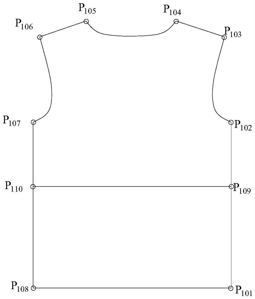
[0064] S1. Extract the vertices of the multi-segment curves in each pattern with a stitching relationship, and record them as the first projection point group corresponding to each pattern. Each point will record its parameter value on the curve. The first projection point group is as follows Three kinds: outer ring point group, inner ring point group and inner curve point group.
[0065] S2. Sort the first projection point groups corresponding to each pattern according to the curve parameter value from small to large to form a curve corresponding to each pattern. The curve is divided into an outer loop curve, an inner loop curve and an inner curve.
[0066] S3, optimize the outer ring curve, inner ring curve and inner curve corresponding to each pattern, and the specific steps are as follows:
[0067] S3.1. Intersect th...
Embodiment 2
[0097] As a further improvement to Embodiment 1, Embodiment 2, a method for aligning pattern mesh vertices based on stitching relationship, further includes
[0098] Step S10, in step S9, the stitched and aligned pattern mesh vertex V is obtained i After that, the mesh shape can be adjusted by adjusting mesh vertices V i The position of Vi is further changed, and the new coordinates of Vi are obtained by calculating the average coordinates of the mesh vertices adjacent to Vi:
[0099]
[0100] In the formula, V i Represents the current mesh vertex, V j means all and V i Connected mesh vertices, t represents the number of mesh vertices adjacent to Vi; i, j, and t are all positive integers. like Figure 12 As shown in the figure, by adjusting the position of the mesh vertex Vi and adjusting the mesh shape, the mesh shape is made more reasonable. After the mesh is optimized, both the connection status of the mesh vertices and the uniformity of the mesh edges will be signi...
Embodiment 3
[0103] Embodiment 3 A pattern grid vertex alignment method based on stitching relationship, comprising the following steps:
[0104] S1. Respectively extract the vertices of the multi-segment curves in each pattern with a stitching relationship, and record them as the first projection point group corresponding to each pattern. The first projection point group is divided into three types: the outer ring point group, the inner ring point group and the inner curve point group;
[0105] S2, sorting the first projection point group corresponding to each pattern according to the curve parameter value to form the outer loop curve, inner loop curve and inner curve corresponding to each pattern;
[0106] S3, optimize the outer ring curve, inner ring curve and inner curve corresponding to each pattern, and the specific steps are as follows:
[0107] S3.1. Intersect the inner curve and the outer ring curve corresponding to each pattern, the inner curve and the inner ring curve, and the ...
PUM
 Abstract
Description
Claims
Application Information
 - R&D
- Intellectual Property
- Life Sciences
- Materials
- Tech Scout
- Unparalleled Data Quality
- Higher Quality Content
- 60% Fewer Hallucinations
Browse by: Latest US Patents, China's latest patents, Technical Efficacy Thesaurus, Application Domain, Technology Topic, Popular Technical Reports.
© 2025 PatSnap. All rights reserved.Legal|Privacy policy|Modern Slavery Act Transparency Statement|Sitemap|About US| Contact US: help@patsnap.com