Multi-device real-time communication module
A technology of real-time communication and device communication, applied in the field of communication
- Summary
- Abstract
- Description
- Claims
- Application Information
AI Technical Summary
Problems solved by technology
Method used
Image
Examples
Embodiment 1
[0049] see Figure 1-8 , the present invention provides a kind of technical scheme:
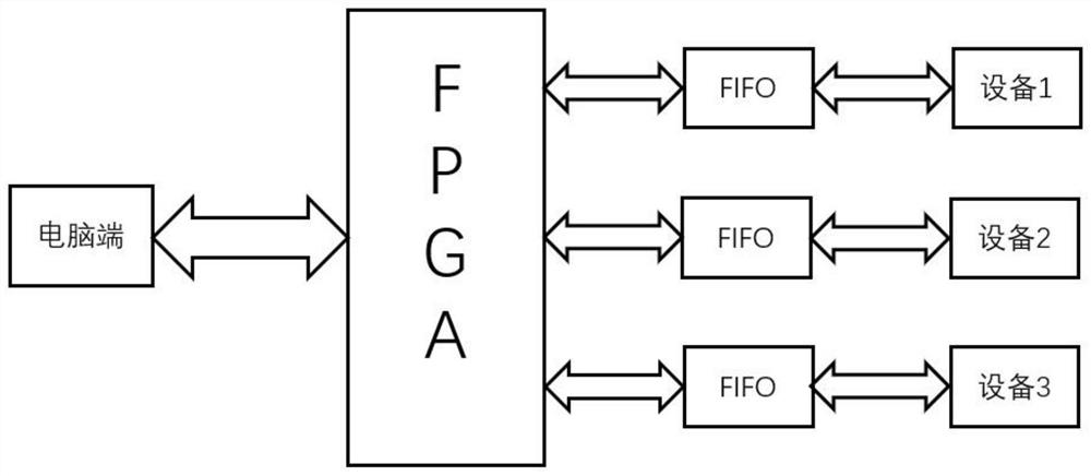
[0050] A multi-device real-time communication module, see figure 1 , The real-time communication module uses FPGA as the core controller to realize the communication between the computer and multiple devices.
[0051] Specifically, the communication modes include single-device communication and multi-device communication.
[0052] Single device communication:
[0053] In the single-device communication mode, the computer selects a device for communication; in this mode, the computer sends commands to the FPGA, and the FPGA sends the valid commands to the corresponding device according to the sent commands, and sends the received feedback data to the computer. ; The format of the command sent is as follows figure 2 .
[0054] like figure 2 , The command format in single-device communication mode consists of command header, valid command and command tail. The command header identifies t...
Embodiment 2
[0075] The present invention provides a technical scheme:
[0076] A multi-device real-time communication module, single-device communication mode:
[0077] First, number the three devices, namely D1, D2, and D3. If you need to read the status of device 1, send "D1E?\r\n". In this command, "D1" is the command header, indicating that this command is to be sent to device 1. "E?" is a valid command to read status. "\r\n" is the end of the command, indicating the end of the command.
[0078] When device 1 receives the turntable read command, device 1 returns the status information "Enable\r\n". When the FPGA receives the status information, add the command header "D1" to get the feedback data "D1Enable\r\n", and then upload the data to the computer. The computer first takes out the first two bytes of the read data according to the length of the command header is two bytes. According to these two bytes, you can know which device the feedback data comes from. Then remove the c...
Embodiment 3
[0080] The present invention provides a technical scheme:
[0081] A multi-device real-time communication module, multi-device communication mode:
[0082] The computer sends a multi-device communication request "CM1R\r\n" to the FPGA. Among them, "CM1" is the command header, indicating that this is a multi-device communication request command. "R" indicates read status. "\r\n" is the command tail. When the FPGA receives this command, it sends a read status command to the three devices at the same time. In this case, we need to read the operating status, voltage value, current value, power and temperature value of the three devices respectively.
[0083]The FPGA first sends "E?\r\n" to the first device, and the device sends back the feedback data "Enable\r\n". Then the FPGA sends "V?\r\n" to the first device, and the device sends back the feedback data "3.5643V\r\n". The FPGA continues to send "A?\r\n" to the first device, and the device sends back the feedback data "345...
PUM
 Abstract
Description
Claims
Application Information
 - R&D
- Intellectual Property
- Life Sciences
- Materials
- Tech Scout
- Unparalleled Data Quality
- Higher Quality Content
- 60% Fewer Hallucinations
Browse by: Latest US Patents, China's latest patents, Technical Efficacy Thesaurus, Application Domain, Technology Topic, Popular Technical Reports.
© 2025 PatSnap. All rights reserved.Legal|Privacy policy|Modern Slavery Act Transparency Statement|Sitemap|About US| Contact US: help@patsnap.com


