
Eureka
For R&D, Eureka makes reading and utilizing patents & technical documents easy.
Eureka AIR
Designed for self-driven R&D workflows. Generate viable solutions, solve complex R&D challenges, empower your innovation with AI.

Eureka Materials
Designed for material experts only. Revolutionize your material R&D, from search, analyze, to developing new materials.

TechResearch
Generate reliable direction feasibility study reports for your R&D in just a few steps.

TechSeek
Discover and master advanced knowledge NOW. Basics, ideas, possibilities, all at once.

TechMind
As an expert in R&D Theories, TechMind can generates customized viable solutions instantly.

TechRisk
Analyze your overall solution with one click, know your potential R&D risks in advance.

TechMonitor
Get weekly tech updates, stay abreast of the latest tech innovations and key insights.
Cover for fiber optic ferrule and ferrule pusher
A technology for fiber optic sleeves and pushers, which is applied in the field of covering parts for optical fiber sleeves and sleeve pushers, and can solve the problem of damage to the sleeve pusher or optical fiber of the optical fiber sleeve, scratching the optical fiber, easy generation of debris or Dust and other issues
- Summary
- Abstract
- Description
- Claims
- Application Information
AI Technical Summary
Problems solved by technology
Method used
Image

Examples
Embodiment Construction
[0032] Reference will now be made in detail to one or more presently preferred embodiments of the present invention, examples of which are illustrated in the accompanying drawings. Wherever possible, the same reference numbers will be used throughout the drawings to refer to the same or like parts.
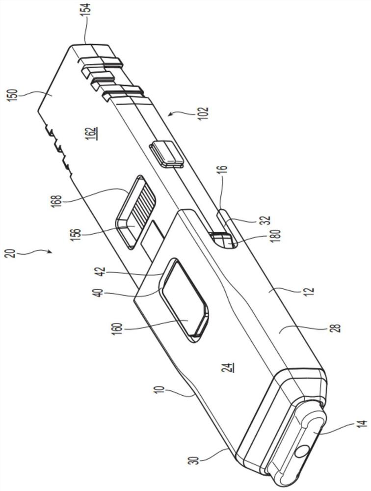
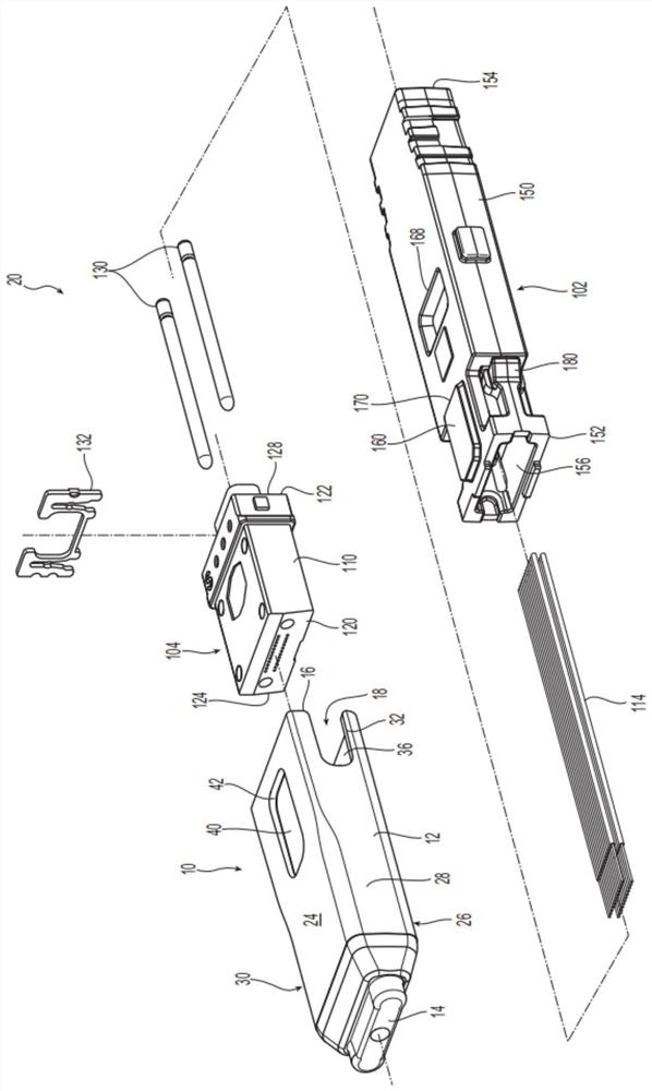
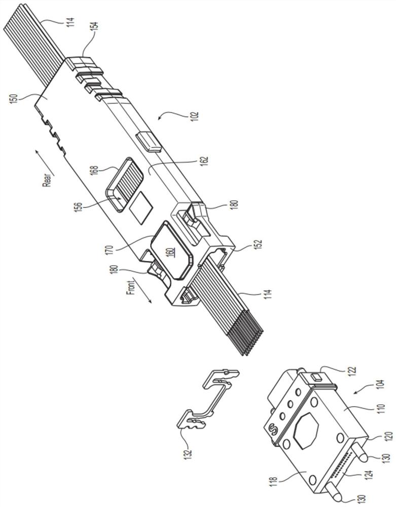
[0033] Applicants note that the term "front" or "forward" means the direction in which a fiber optic connector and / or ferrule will meet another fiber optic connector or device, whereas the use of the term "rear" or "rearward" means Refers to the direction from which the fiber enters the fiber optic ferrule, fiber optic connector, or ferrule pusher. Thus, each component will have a front and a back, and the two front or forward portions of the fiber optic ferrule will be joined to each other. Thus, in figure 1 , the "front" of the fiber assembly is located figure 1 to the left and "forward" is towards the left and out of the page. "Backward" or "rear" is the portion of the fibe...
PUM
 Abstract
Description
Claims
Application Information
 - R&D Engineer
- R&D Manager
- IP Professional
- Industry Leading Data Capabilities
- Powerful AI technology
- Patent DNA Extraction
Browse by: Latest US Patents, China's latest patents, Technical Efficacy Thesaurus, Application Domain, Technology Topic, Popular Technical Reports.
© 2024 PatSnap. All rights reserved.Legal|Privacy policy|Modern Slavery Act Transparency Statement|Sitemap|About US| Contact US: help@patsnap.com