
Equipment for cutting cable moving in horizontal direction

A horizontal direction, cable technology, applied in the field of cable processing, can solve the problems of uneven incision, poor appearance, difficult cable length measurement, etc., and achieve the effect of accurate cutting length and uniform incision

Inactive Publication Date: 2022-08-02
南通佳恒线缆材料有限公司
View PDF7 Cites 2 Cited by
  • Summary
  • Abstract
  • Description
  • Claims
  • Application Information

AI Technical Summary

Problems solved by technology

[0003] Most of the existing cable cutting equipment winds the wire through two rollers, and then cuts it with a cutter. In this cutting method, the cable is easy to be in a loose state during the cutting process, and the cable cannot be cut during the transmission process. Keep moving horizontally, resulting in irregular cuts at both ends of the cable cutting area during cutting, which will affect the normal use later and reduce its appearance. At the same time, the cuts are uneven, making it difficult to accurately measure the length of the cable

Method used


Image

  • Equipment for cutting cable moving in horizontal direction
  • Equipment for cutting cable moving in horizontal direction
  • Equipment for cutting cable moving in horizontal direction

Examples


Embodiment 1

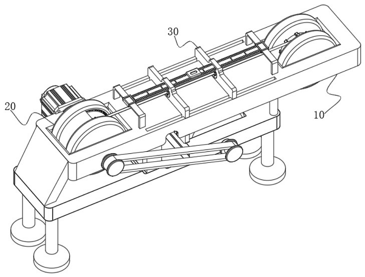
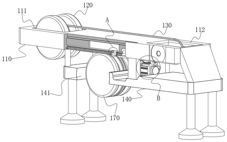
[0046] see Figure 1-Figure 11 As shown, the purpose of this embodiment is to provide a device for cutting cables moving in a horizontal direction, including an operation table 10 and a cable tightening mechanism 20 installed on the top side of the operation table 10. The operation table 10 Include at least:

[0047] The upper plate 110, a front groove 111 is provided on one side of the top of the upper plate 110, and a rear groove 112 is provided on the other side of the top of the upper plate 110;

[0048] a cable pay-off reel 120, the cable pay-off reel 120 is arranged at the inner end of the front groove 111, and the cable pay-off reel 120 is rotatably connected with the front groove 111;

[0049] The cable body 130, one end of the cable body 130 is connected to the side of the cable pay-off tray 120 in a spiral manner;

[0050] the lower plate 140, the lower plate 140 is arranged at the bottom end of the upper plate 110, and the bottom groove 141 is arranged on one side...


PUM


Abstract

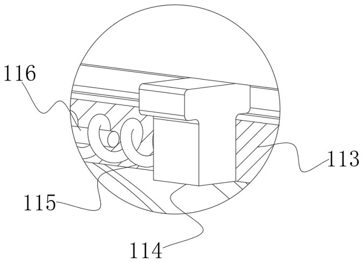
The invention relates to the technical field of cable processing, in particular to equipment for cutting a cable moving in the horizontal direction. The cable tightening device comprises an operation table and a cable tightening mechanism installed on one side of the top end of the operation table, the operation table comprises an upper plate, a cable pay-off reel is arranged on one side of the top end of the upper plate, a rear groove is formed in the other side of the top end of the upper plate, the cable tightening mechanism comprises a cable pulling disc, a plurality of inner grooves are formed in the inner side of the cable pulling disc, and T-shaped blocks are arranged at the inner ends of the inner grooves; the bottom end of the T-shaped block is connected with a pair of extrusion springs, contraction blocks are arranged on the two sides of the top end of the T-shaped block and matched with the T-shaped block in an inserted mode, and the side faces of the contraction blocks are connected with a plurality of reset springs. According to the cable cutting device, the tensioning function of a cable body is achieved through the arranged cable tightening mechanism, so that it is guaranteed that the cable body moves horizontally in the conveying process, meanwhile, during cutting, the cable body is in a straightened state, a notch is more uniform, it is guaranteed that the cutting length is more accurate, and errors are avoided, and the later use effect is not affected.

Description

technical field [0001] The present invention relates to the technical field of cable processing, in particular to a device for cutting cables moving in a horizontal direction. Background technique [0002] Cable is a general term for optical cables, cables and other items. There are many uses of cables, mainly used for multiple functions such as control and installation, connecting equipment, and power transmission. During the process, the cables need to be cut to suit different occasions. [0003] Most of the existing cable cutting equipment is wound through two rollers, and then cut by a cutter. In this cutting method, the cable is easily in a loose state during the cutting process, and the cable cannot be transmitted during the transmission process. Keep moving horizontally, resulting in irregular incisions at both ends of the cable cutting area during cutting, which will affect the normal use in the later period and reduce its appearance. At the same time, the incision...

Claims


Application Information

Patent Timeline
Patent Type & Authority Applications(China)
IPC IPC(8): B21F11/00H02G1/00
CPCB21F11/00H02G1/005
Inventor 许波建
Owner 南通佳恒线缆材料有限公司
Learn More