Device for testing friction performance of clutch friction plate

A friction performance and testing device technology, applied in measuring devices, mechanical devices, workpiece clamping devices, etc., can solve the problem of difficulty in ensuring the fit between the friction plate and the detection head.

Active Publication Date: 2022-08-09
EASTERN GANSU UNIVERSITY
View PDF7 Cites 0 Cited by
  • Summary
  • Abstract
  • Description
  • Claims
  • Application Information

AI Technical Summary

Problems solved by technology

[0003] The performance of the friction clutch depends on the performance of its friction plate. In order to ensure the performance of the friction clutch during use, it is necessary to carry out sampling inspection on the friction plate of the friction clutch. In the prior art, the friction plate is pressed against the rotating detection head. Realize the detection of the friction plate, but this method requires manual use of clamps to clamp the friction plate, and through manual clamping, it is difficult to ensure the fit between the friction plate and the detection head during the detection process

Method used


Image

  • Device for testing friction performance of clutch friction plate
  • Device for testing friction performance of clutch friction plate
  • Device for testing friction performance of clutch friction plate

Examples


Embodiment 1

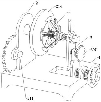
[0030] The present invention provides such as Figure 1 to Figure 10 A friction performance test device of a clutch friction plate as shown includes a supporting assembly 1, a rotating assembly 2, an adjusting assembly 3 and a clamping assembly 4, and the two ends of the upper surface of the supporting assembly 1 are respectively provided with a rotating assembly 2 and an adjusting assembly 3, A clamping assembly 4 is arranged between the rotating assembly 2 and the adjusting assembly 3 .

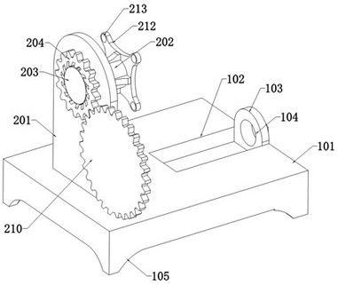
[0031] The support assembly 1 includes a support base 101. A chute 102 is provided in the middle of one end of the upper surface of the support base 101. A support plate 103 is fixedly connected to one end of the slot of the chute 102. The four corners of the lower surface of the seat 101 are fixedly connected with feet 105 .

[0032] The rotating assembly 2 includes a fixed plate 201, the middle of the fixed plate 201 is movably connected with a rotating rod 202 through a bearing, one end...

Embodiment 2

[0041] Based on the previous embodiment, under the long-term use of the above-mentioned device, it is easy to cause different degrees of wear of the clamping block 405. Since the position of the clamping block 405 is determined by the position of the movable sleeve 410, the above-mentioned device cannot be adjusted according to the degree of wear of the clamping block 405. The clamping block 405 is closely attached to the friction plate. At the same time, due to the different thickness of the friction plate, the above device cannot adjust the clamping position of the clamping block 405 and the friction plate according to the thickness change of the friction plate. If the thickness of the friction plate is smaller than the clamping block 405, As a result, the clamping block 405 protrudes from the friction plate, which affects the performance detection of the friction plate. If the thickness of the friction plate is larger than that of the clamping block 405, the clamping area of ...


PUM


Abstract

The invention discloses a clutch friction plate friction performance testing device, and relates to the technical field of clutch accessory detection, and the clutch friction plate friction performance testing device comprises a supporting assembly and a rotating assembly, and the two ends of the upper surface of the supporting assembly are provided with the rotating assembly and an adjusting assembly respectively; a clamping assembly is arranged between the rotating assembly and the adjusting assembly; the clamping assembly comprises a clamping seat, one end of the clamping seat is fixedly connected with a stud, one end of the stud is fixedly connected with a fixing disc, and the outer side of the stud is connected with a positioning sleeve in a sleeving mode; by arranging the clamping assembly, the clutch friction plate can be supported and fixed, the movable arm is arranged on one side of the clamping block, the movable sleeve is arranged at one end of the movable arm, and the movable sleeve can adjust the position of the clamping block, so that the device can clamp and fix the clutch friction plates of various specifications.

Description

technical field [0001] The invention relates to the technical field of clutch fitting detection, in particular to a friction performance test device of a clutch friction plate. Background technique [0002] The friction clutch is one of the important parts of mechanical transmission. It uses the mechanical friction between the friction surfaces to transmit the torque from the driving shaft to the driven shaft, and can make the host and the driven shaft engage or disengage according to the work needs. Generally, friction clutches are often used in propulsion systems of various powers with a non-reversing engine (high-speed diesel engine) as the main engine. In recent years, clutches have also been widely used in single or parallel transmission units of high-power medium-speed diesel engines. The function of the friction clutch not only transmits power, but also engages or disengages the driving shaft and the driven shaft at the appropriate time, which is conducive to the no-...

Claims


Application Information

Patent Timeline
IPC IPC(8): G01N3/56G01N3/02G01N3/04G01N19/02G01M13/022B25B11/00
CPCG01N3/56G01N3/02G01N3/04G01N19/02G01M13/022B25B11/00
Inventor 贾利平
Owner EASTERN GANSU UNIVERSITY
Why Eureka
Try Eureka