
Power supply control device and method for mobile communication base station

A mobile communication base station, power supply control technology, applied to circuit devices, battery circuit devices, substation/switch layout details, etc. problem, to achieve a good shock absorption effect

Pending Publication Date: 2022-08-09
吴结心
View PDF0 Cites 0 Cited by
  • Summary
  • Abstract
  • Description
  • Claims
  • Application Information

AI Technical Summary

Problems solved by technology

[0004] 1. The power supply control device of the existing mobile communication base station will generate severe vibration when the train passes by, which will lead to the problem of breaking in and out of the connection between the bottom of the power supply device and the ground;
[0005] 2. The power supply control device of the existing mobile communication base station is inconvenient to fix the outer walls of lines with different diameters, thus greatly reducing the effect of fixing the lines by the threading plate;

Method used


Image

  • Power supply control device and method for mobile communication base station
  • Power supply control device and method for mobile communication base station
  • Power supply control device and method for mobile communication base station

Examples


Embodiment 1

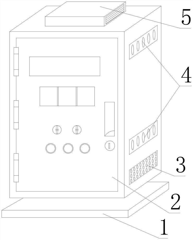
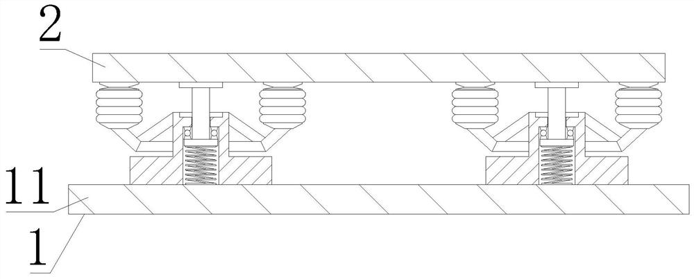
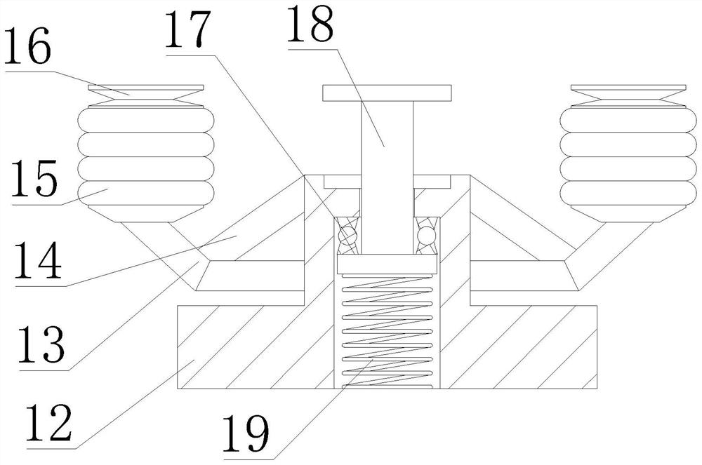
[0044] First, as Figure 1-5As shown, the present invention provides a power supply control device for a mobile communication base station, comprising a power supply control device main body 2, a base 1 is fixedly installed at the bottom of the power supply control device main body 2, and inlets are opened at the bottoms of the left and right sides of the power supply control device main body 2. Air port 3, threading plates 4 are fixedly installed on the left and right sides of the power supply control device main body 2, and a radiator 5 is fixedly installed on the top of the power supply control device main body 2. The base 1 includes an I-shaped guide post 18, and the top of the I-shaped guide post 18 is installed. It is fixedly installed with the bottom of the main body 2 of the power supply control device, the outer wall of the I-shaped guide post 18 is movably sleeved with a guide sleeve support 12, the bottom of the guide sleeve support 12 is fixedly installed with a sup...

Embodiment 2

[0047] like Figure 1-5 As shown, on the basis of Embodiment 1, the present invention provides a technical solution: preferably, a support bracket 13 is fixedly connected to the middle of the outer wall of the guide sleeve support 12, and a reinforcement plate 14 is fixedly connected to the front of the support bracket 13. , the top of the reinforcing plate 14 is fixedly installed with an annular buffer spring washer 15, the top of the annular buffer spring washer 15 is fixedly installed with an I-shaped tray 16, and the bottom of the annular airbag cushion 17 and the bottom of the inner cavity of the guide sleeve support 12 are overlapped with The spring 19, the outer wall of the I-shaped guide post 18 and the top of the inner wall of the guide sleeve support 12 are movably sleeved with an annular airbag cushion 17.

[0048] In this embodiment, the bottom of the main body 2 of the power supply control device is supported by the action of the annular buffer spring 15 and the s...

Embodiment 3

[0050] like Figure 1-5 As shown, on the basis of Embodiment 1, the present invention provides a technical solution: preferably, threaded sleeves 43 are fixedly sleeved on both sides of the front of the lower clamping plate 42, and the inner wall of the threaded sleeve 43 is located between the upper clamping plate 41 and the upper clamping plate 41. The front side of the lower clamping plate 42 is threadedly connected with a threaded rod 44, the rubber wire sleeve 47 includes an upper clamping sleeve 471, the outer wall of the upper clamping sleeve 471 is clamped with the bottom of the upper clamping plate 41, and the bottom of the upper clamping sleeve 471 is clamped with a lower clamping sleeve. Sleeve 473, the upper ferrule 471 and the inner wall of the lower ferrule 473 are fixedly connected with anti-skid protruding strips 472.

[0051] In this embodiment, through the action of the threaded sleeve 43 and the threaded rod 44, the connection between the upper clamping plat...


PUM


Abstract

The invention discloses a power supply control device and method for a mobile communication base station, and relates to the technical field of mobile communication base stations, the power supply control device comprises a power supply control device main body, the bottom of the power supply control device main body is fixedly provided with a base, and the bottoms of the left and right sides of the power supply control device main body are provided with air inlets; and threading plates are fixedly mounted on the left side and the right side of the power supply control device main body. The bottom of the power supply control device main body is supported under the action of an annular buffer spring pad and a spring, so that the power supply control device main body has a good damping effect, and the problem that the connecting part between the bottom of the power supply control device and the ground is broken due to the fact that the vibration amount is too large when a train passes through is solved; and the bottom of the annular buffer spring washer is supported under the action of the supporting bracket and the reinforcing plate, so that the annular buffer spring washer is conveniently supported, and the purpose of supporting the bottom of the power supply control device main body is achieved.

Description

technical field [0001] The present invention relates to the technical field of mobile communication base stations, in particular to a power supply control device and method for a mobile communication base station. Background technique [0002] With the development of social economy, people have higher and higher requirements for the quality of mobile communication services. While continuously developing mobile communication base station technology, mobile communication service providers provide the largest possible coverage by adding a large number of base stations to meet the needs of Users have requirements for the quality of mobile communication services, but in some special usage scenarios, relying on ordinary base stations cannot guarantee the quality of communication services. High-speed railways are such a special usage scenario. In order to solve the problem that the quality of mobile communication service cannot be guaranteed on high-speed trains, mobile communicati...

Claims


Application Information

Patent Timeline
Patent Type & Authority Applications(China)
IPC IPC(8): H02B1/54H02B1/50H02B1/20H02J7/00
CPCH02B1/54H02B1/50H02B1/20H02J7/00Y02E60/10
Inventor 吴结心
Owner 吴结心
Learn More