Transmission system and method for encoding speech with improved pitch detection

A transmission system and tone technology, applied in the field of transmission systems, can solve problems such as the decrease in the reliability of tone detection

Inactive Publication Date: 2004-06-30
KONINKLIJKE PHILIPS ELECTRONICS NV
View PDF0 Cites 0 Cited by
  • Summary
  • Abstract
  • Description
  • Claims
  • Application Information

AI Technical Summary

Problems solved by technology

This can result in less reliable tone detection

Method used


Image

  • Transmission system and method for encoding speech with improved pitch detection
  • Transmission system and method for encoding speech with improved pitch detection
  • Transmission system and method for encoding speech with improved pitch detection

Examples


Embodiment Construction

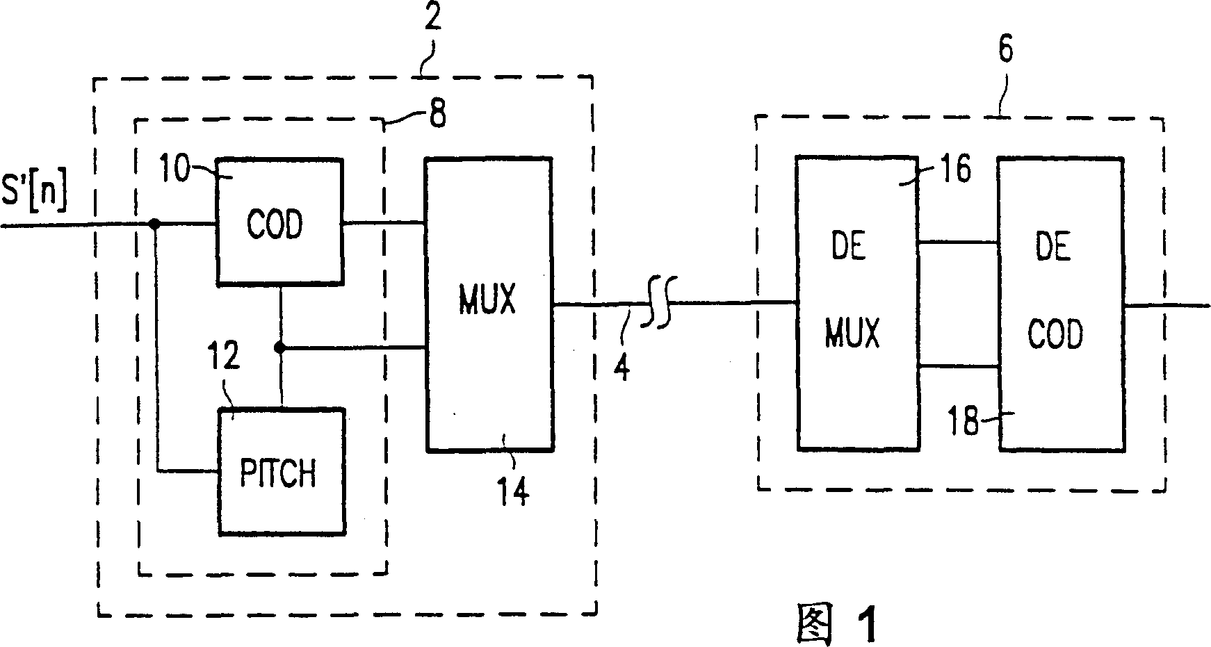
[0026] In the transmission system shown in Fig. 1, a digital speech signal S'[n] is applied to the transmitter 2. In this transmitter 2, the speech signal S'[n] is applied to the encoder, wherein the speech signal S'[n] is applied to the pitch detector 12 and the pitch-synchronous coding device 10. An output of the pitch detector 12 with pitch information as an output signal is connected to an input of a multiplexing processor 14 and to a first input of the pitch synchronous encoding device 10 . An output of the pitch synchronous encoding device 10 is connected to a second input of a multiplexing processor 14 . The output of the multiplexing processor 14 is coupled to the output of the transmitter 2 .

[0027] The output of the transmitter 2 is connected to the input of the receiver 6 via a path 4 . The input of the receiver 6 is connected to the input of the demultiplexer 16 . A first output of the demultiplexer is connected to a first input of a pitch synchronous decoder ...


PUM


Abstract

A transmission system contains a speech coder which utilizes a pitch detector that is arranged to select a characteristic auxiliary signal portion from the signal to be coded in order to improve the quality of the pitch detection. The pitch is found by searching in the speech signal for signal portions that correspond to the characteristics auxiliary signal portion and by calculating the time difference between the respective signal portions.

Description

technical field [0001] The invention relates to a transmission system comprising a transmitter with an encoder deriving a coded signal from a quasi-periodic signal, the transmitter being arranged to transmit the coded signal to a receiver via a medium, the coder comprising a A pitch detector for deriving pitch information from a quasi-periodic signal. [0002] The invention also relates to an encoder, a detector for detecting the period of a quasi-periodic signal and a pitch detection method. Background technique [0003] From Y.M.Cheng and D.O.Shunghnessy in IEEE Transaction onAcoustics, "Speech and Signal Processing" (Speech and Signal Proces sing), Vol.ASSP-23, pp.418-423, 1976 "Glottic closure instant and periodic A tone detector defined in the opening paragraph for use in transmission systems is known from "Automatic and Reliable Estimation of Glottal Closure lnstant and Period". [0004] Such transmission systems are used, for example, to transmit speech signals via ...

Claims


Application Information

Patent Timeline
Patent Type & Authority Patents(China)
IPC IPC(8): G10L25/06G10L25/90
CPCG10L25/90G10L25/06G10L2019/0011
Inventor R·陶里R·J·施卢伊特E·卡思曼
Owner KONINKLIJKE PHILIPS ELECTRONICS NV
Why Eureka
Try Eureka