Sound measuring apparatus and method, and audio signal processing apparatus

a technology of sound measurement and audio signal, applied in the direction of transducer details, instruments, computing, etc., can solve the problems of delay time whose length and the measurement of test signals, and the signal-based measurement technique of the related art has limitations

Inactive Publication Date: 2011-05-24
SONY CORP
View PDF11 Cites 157 Cited by
  • Summary
  • Abstract
  • Description
  • Claims
  • Application Information

AI Technical Summary

Benefits of technology

[0020]Since the measurable delay time is limited to within one cycle of the test signal, one of the current approaches for allowing measurement of a longer delay time is to increase the number of samples of the test signal.
[0021]Actually, the test signal is output from the speaker so that values of the test signal are output one-by-one according to a constant clock (for example, 44.1 kHz). If the number of samples of the test signal increases, the time length of one cycle of the test signal can become long correspondingly. Therefore, a longer delay time can be measured.
[0029]According to an embodiment of the present invention, by expanding a test signal in the time axis, a longer delay time can be measured. Thus, a long delay time can be measured regardless of the number of samples of the test signal.
[0030]According to an embodiment of the present invention, therefore, since the expansion of a test signal in the time axis allows measurement of a longer delay time, a long delay time can be measured regardless of the number of samples of the test signal.
[0032]Further, the audio signal processing apparatus according to the embodiment of the present invention can adjust a delay time of an audio signal to be output from the speaker according to the delay time measured using the technique of the embodiment of the present invention.

Problems solved by technology

However, such a test-signal-based measurement technique of the related art has a limitation in that a delay time whose length is up to only one cycle of the test signal can be measured.
As can be understood from the above description, the technique of the related art shown in FIG. 12 does not allow accurate measurement of a delay time unless the length of the delay time is within one cycle of the test signal.

Method used


Image

  • Sound measuring apparatus and method, and audio signal processing apparatus
  • Sound measuring apparatus and method, and audio signal processing apparatus
  • Sound measuring apparatus and method, and audio signal processing apparatus

Examples


first embodiment

[0089]FIG. 3 is a diagram showing a delay time measurement process according to the first embodiment.

[0090]In FIG. 3, the waveforms of a TSP signal, an impulse signal that the TSP signal is based on, an output signal that is output from each of the speakers SP based on the TSP signal according to the method of the first embodiment, and a picked up audio signal obtained by picking up the output signal using the microphone M1 are illustrated with respect to a time axis T.

[0091]Each of the waveforms shown in FIG. 3 is sectioned by frames, and each frame represents one cycle of a TSP signal as a test signal.

[0092]For the convenience of description, the delay time measurement process for one of the speakers SP will be described. The delay times for the speakers SP may be measured by repeatedly performing a similar measurement process for each of the speakers SP.

[0093]In FIG. 3, the waveform of the TSP signal is a waveform obtained when values of the TSP signal stored as the test signal 1...

second embodiment

[0155]As described above, one effective technique for improving the measurement accuracy using the technique of the first embodiment is to set a closer expansion factor from a measurement result obtained with a high expansion factor and to perform another measurement with the set expansion factor. In any case, the finally measured delay time DT2 is obtained based on the expanded TSP signal, and it is difficult to provide high-accuracy measurement on a clock-by-clock basis, as in the existing method.

[0156]Accordingly, the second embodiment provides a technique capable of measuring a longer delay time according to the defined expansion factor according to the technique of the first embodiment and capable of providing high-accuracy measurement on a clock-by-clock basis according to the existing technique.

[0157]For easy understanding of the technique of the second embodiment, problems with the existing technique will be reconsidered. As previously described in comparison between FIGS. 1...


PUM


Abstract

A sound measuring apparatus for measuring a sound-arrival delay time from a speaker to a microphone on the basis of a result obtained by outputting a test signal from the speaker and picking up the test signal using the microphone includes the following elements. A control unit performs control so that the test signal is expanded in a time axis and is then output from the speaker. A delay time measuring unit measures an expansion-based measured delay time on the basis of a delay time that is measured on the basis of a time difference between the test signal expanded in the time axis and output from the speaker and a signal obtained from the microphone by picking up the output expanded test signal, and obtains the sound-arrival delay time as the expansion-based measured delay time.

Description

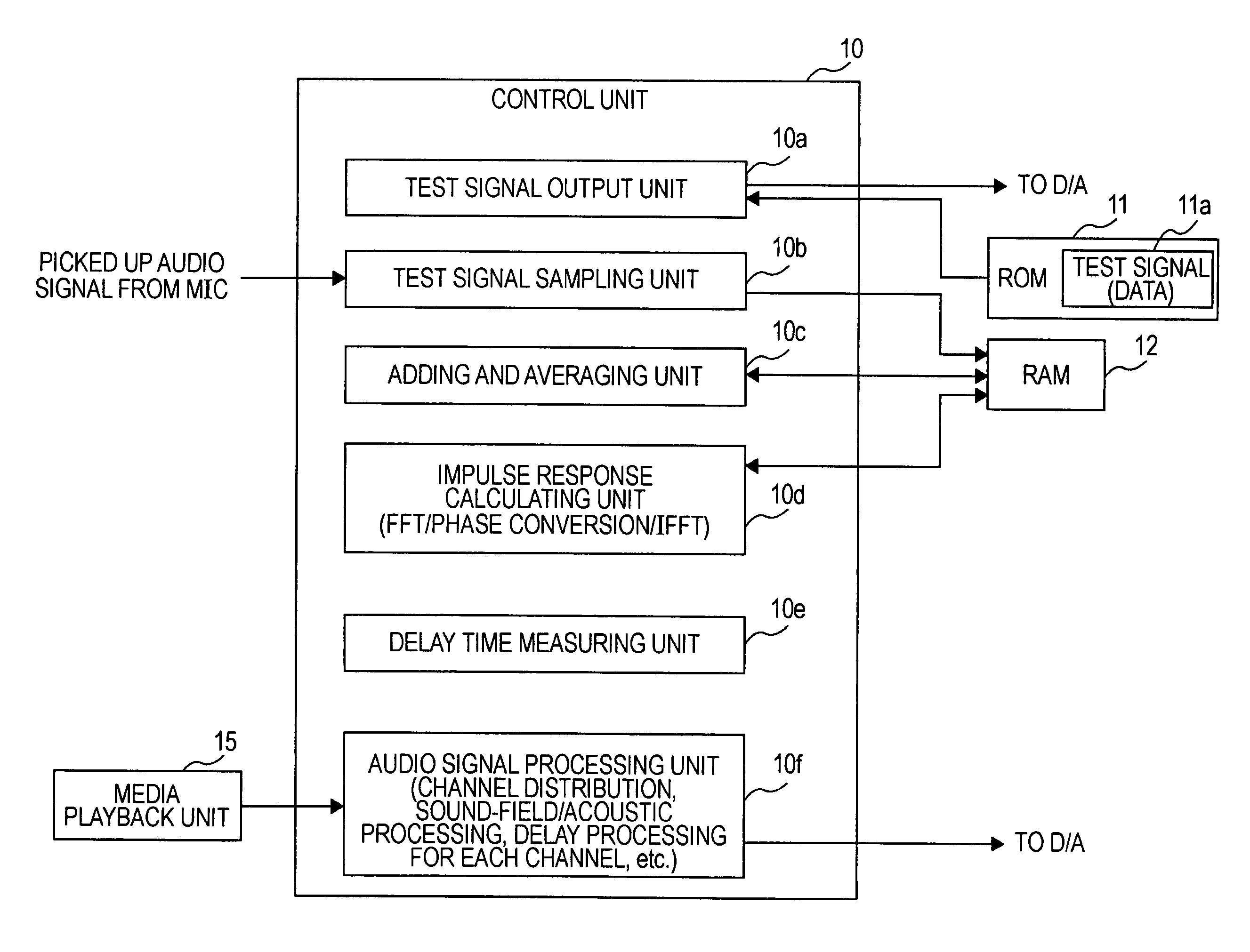
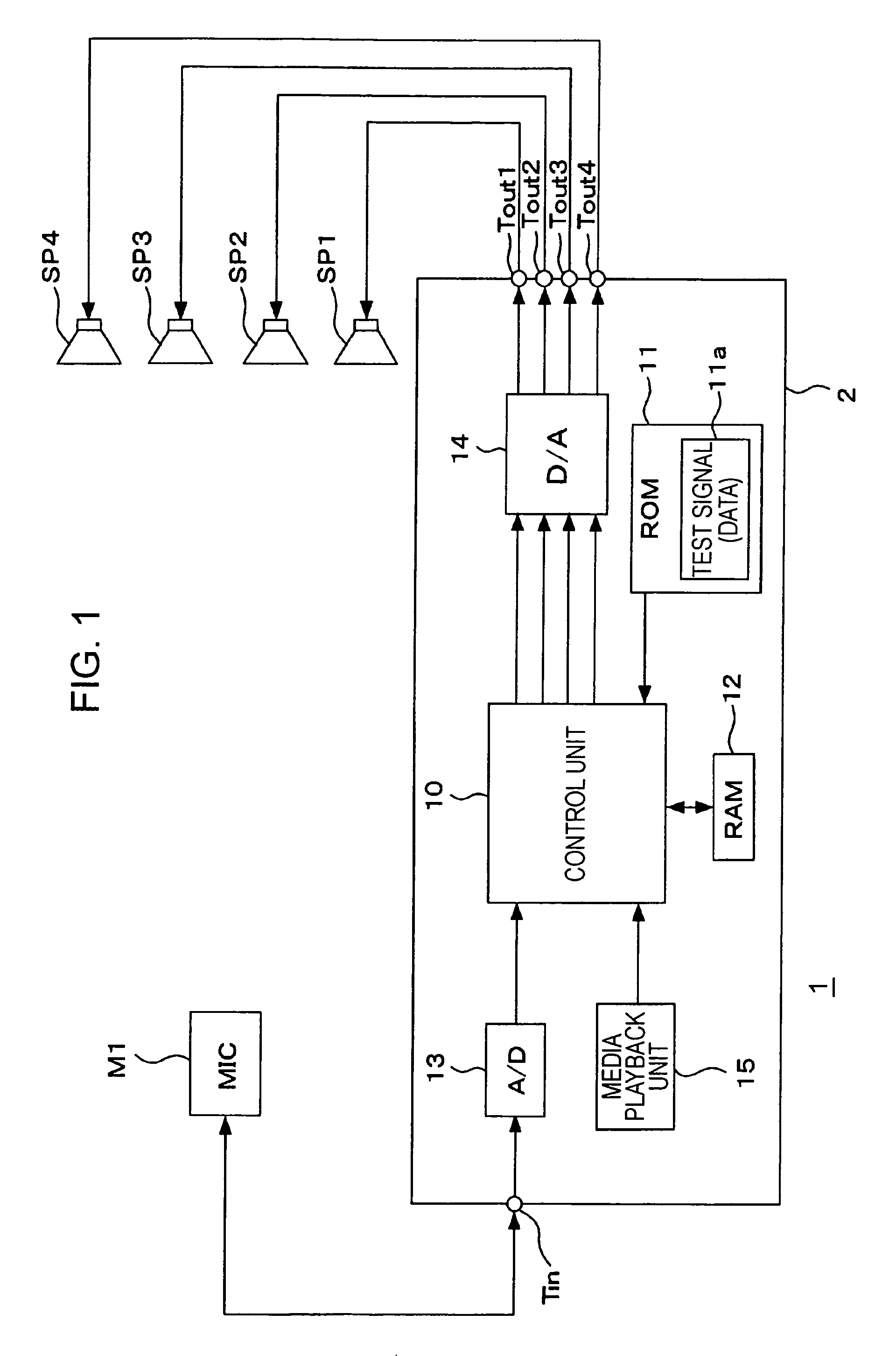
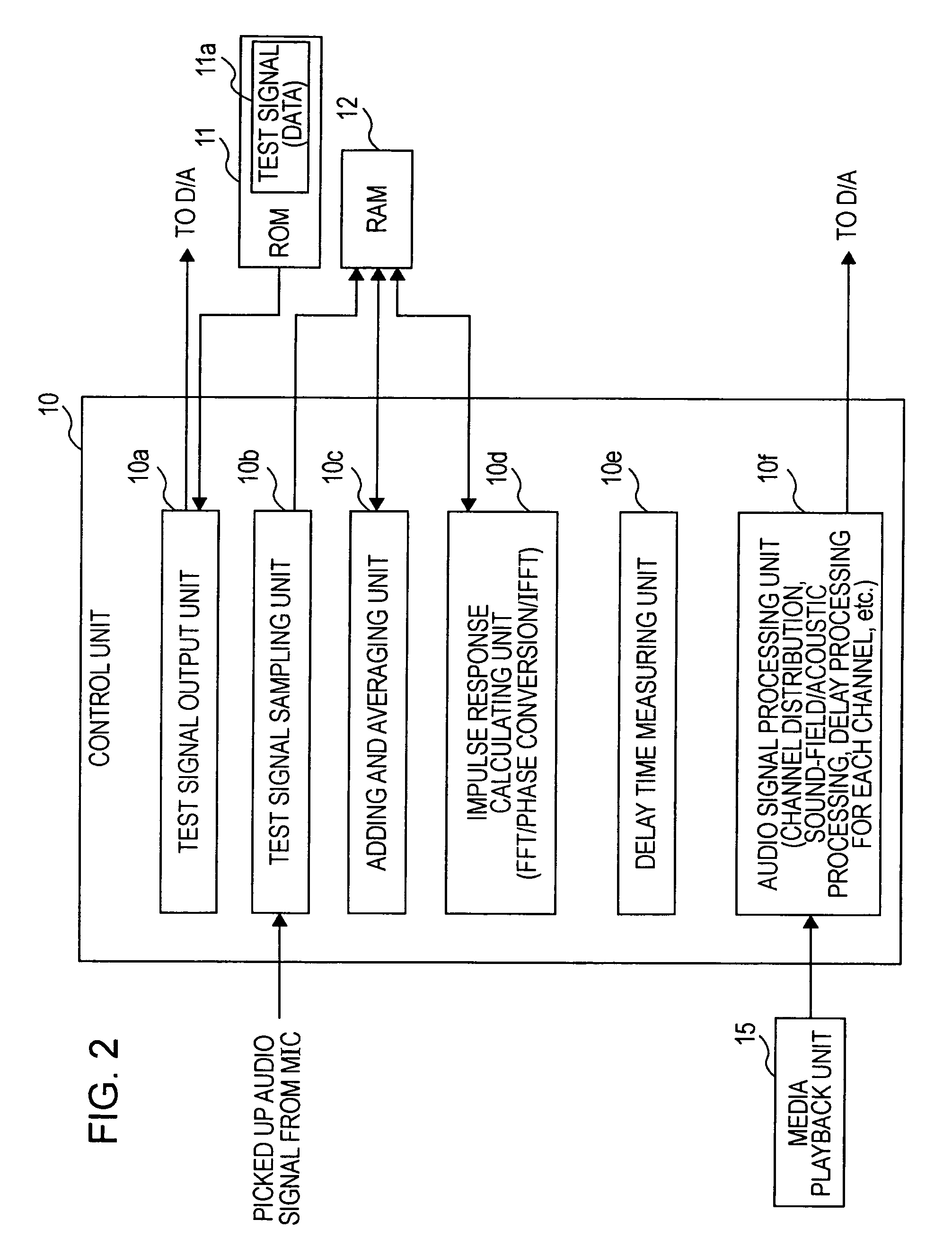
CROSS REFERENCES TO RELATED APPLICATIONS[0001]The present invention contains subject matter related to Japanese Patent Application JP 2005-302984 filed in the Japanese Patent Office on Oct. 18, 2005, the entire contents of which are incorporated herein by reference.BACKGROUND OF THE INVENTION[0002]1. Field of the Invention[0003]The present invention relates to sound measuring apparatuses and methods and to audio signal processing apparatuses. More specifically, the present invention relates to a sound measuring apparatus and method for measuring a sound-arrival delay time from a speaker to a microphone on the basis of a result obtained by outputting a test signal from the speaker and picking up the test signal using the microphone. The present invention further relates to an audio signal processing apparatus having a function for measuring the sound-arrival delay time.[0004]2. Description of the Related Art[0005]In audio systems of the related art, in particular, an audio system in ...

Claims


Application Information

Patent Timeline
Patent Type & Authority Patents(United States)
IPC IPC(8): H04R29/00
CPCH04S7/301H04R2499/13H04S1/00H04S7/307H04S3/00
Inventor KINO, YASUYUKI
Owner SONY CORP
Why Eureka
Try Eureka