Method and system for time-delay path planning

A delay path and path technology, applied in the field of intelligent transportation, can solve the problems of sparse data information, weak regularity, and increased driving time, and achieve the effect of wide data range, large data sample size, and improved accuracy

Active Publication Date: 2014-10-29
BEIJING SOGOU INFORMATION SERVICE +1
View PDF11 Cites 30 Cited by
  • Summary
  • Abstract
  • Description
  • Claims
  • Application Information

AI Technical Summary

Problems solved by technology

[0006] However, this scheme only considers the historical road conditions. In fact, the road conditions are not fixed, but change in real time. Especially for some long-distance road sections, it is often encountered that it is currently smooth but becomes congested when it arrives.
The data information of this scheme is sparse and limited in scope: only a small number of taxis and buses are equipped with speed recorders, so the obtained historical data is only valid for the main road, and the scope of action is limited, and all samples are not evenly distributed among all vehicles , the samples in the historical data are not uniform enough, which may also lead to inaccurate results
In addition, it is not enough information to predict future road conditions only through the historical traffic conditions of the road, especially for road conditions that are not regularly changed.
Since the road conditions of each road section on which path planning is based will change continuously during the current vehicle's driving process, when the current vehicle travels to a certain road section for path planning before, the road conditions of this road section are likely to change from good to bad. Make users likely to drive on roads that are predicted to be in good condition but actually become congested, increasing travel time

Method used


Image

  • Method and system for time-delay path planning
  • Method and system for time-delay path planning
  • Method and system for time-delay path planning

Examples


Embodiment 1

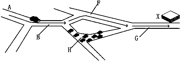
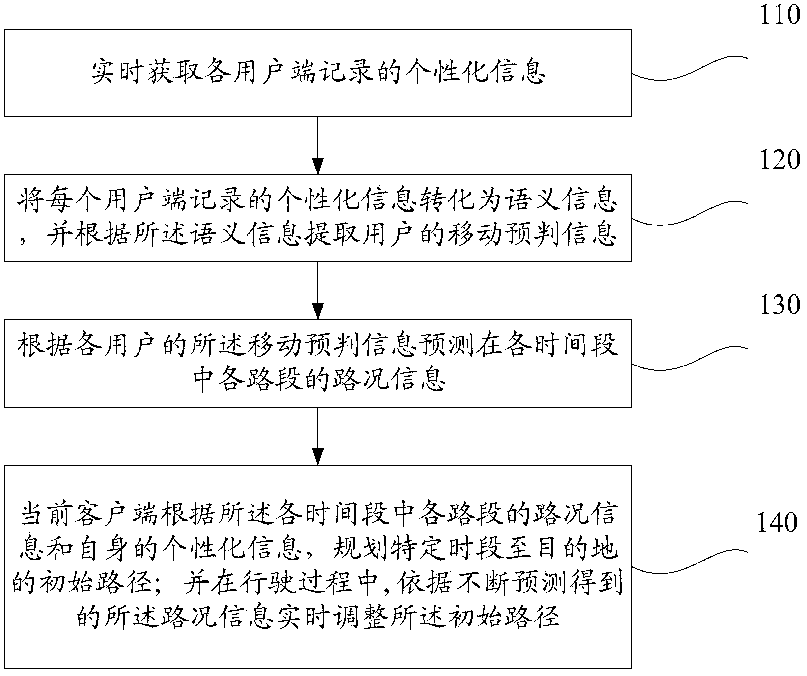
[0061] refer to figure 1 , shows a schematic flowchart of a method for delay path planning according to Embodiment 1 of the present application.

[0062] The embodiment of this application actually includes two aspects:

[0063] First, continuously obtain the personalized information of each corresponding client in real time for analysis to predict the corresponding driving trajectory and driving time of the client, and then predict the road conditions of each road segment in each time period according to the driving trajectory and driving time of each vehicle Information (congestion location and congestion degree, etc.);

[0064] Second, on the basis of the predicted road condition information, plan the initial path from the current location to the destination for the current client, and adjust the initial path according to the ever-changing and predicted road condition information during the driving process of the current client , until the client reaches the destination. ...

Embodiment 2

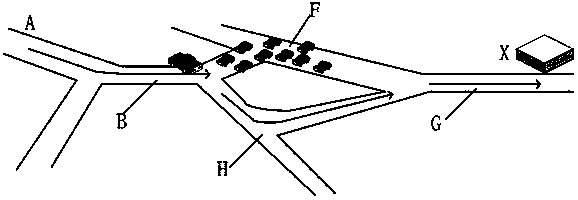
[0121] refer to figure 2 , shows a delay path planning method according to Embodiment 2 of the present application.

[0122] In the embodiment of the present application, in order to improve the accuracy of the road condition information, for the client that has been driving, the real-time basic movement information of the client is extracted to correct the deviation of the user's movement prediction information extracted according to the semantic information.

[0123] In this embodiment, a method for delayed path planning may specifically include:

[0124]Step 210, obtaining the personalized information recorded by each client in real time;

[0125] This step is similar to step 110 and will not be described in detail here.

[0126] Step 220, extracting the real-time basic mobile information of each client;

[0127] In the embodiment of the present application, the current basic mobile information of each client can be extracted in real time, and the basic mobile informati...

Embodiment 3

[0159] refer to Figure 5 , which shows a schematic structural diagram of a delayed path planning system according to Embodiment 3 of the present application, which may specifically include:

[0160] Personalized information extraction module 310, used for real-time acquisition of personalized information recorded by each client;

[0161] Pre-judgment information acquisition module 320, for converting the personalized information recorded by each client into semantic information, and extracting the user's mobile pre-judgment information according to the semantic information;

[0162] Preferably, the personalized information includes text information recorded by the client;

[0163] Further, the pre-judgment information acquisition module includes:

[0164]a semantic analysis unit, configured to perform semantic analysis on the text information to obtain a semantic expression;

[0165] A mobile information extraction unit, configured to extract departure time and correspondi...


PUM


Abstract

Relating to the technical field of intelligent traffic, the invention provides a method and system for time-delay path planning. The method includes: acquiring the personalized information recorded by each client in real time; converting the personalized information recorded by each client into semantic information, and extracting mobile pre-judgement information of users according to the semantic information; forecasting the traffic information of each road section in each period of time according to the mobile pre-judgement information of all the users; planning an initial path to a destination in a specific period of time by a current client according to the traffic information of each road section in each period of time and the individualized information of itself; and in the driving process, adjusting the initial path in real time according to the traffic information obtained by continuous forecast. The method and the system provided by the invention has the characteristics of large data sample size, wide data range and data timeliness, can reduce the prediction result deviation, and can more comprehensively, more accurately and more timely forecast the driving road section with good traffic conditions within certain period of time in the future for users, thus enhancing the accuracy of path forecast and adjustment.

Description

technical field [0001] The present application relates to the technical field of intelligent transportation, in particular to a method and system for delay path planning. Background technique [0002] Road route navigation is a typical application in the technical field of GPS, and it has been widely used at present. In the existing technology, path planning is often based on the topological relationship of the road network, considering the basic attributes of the road network, such as the grade of the road, the number of lanes, the number of intersections, the number of traffic lights and other basic attributes, and using the topology algorithm to give the starting point and Path schemes such as the shortest total distance between the destinations or the shortest total time-consuming. [0003] There are generally two navigation methods in the prior art: [0004] 1. Vehicle navigation based on the basic attributes of the road: According to the basic attributes of the road,...

Claims


Application Information

Patent Timeline
Patent Type & Authority Applications(China)
IPC IPC(8): G01C21/26G01C21/34
CPCG01C21/3415G01C21/3484G01C21/3492
Inventor 张帆柴思远张阔
Owner BEIJING SOGOU INFORMATION SERVICE
Why Eureka
Try Eureka