Ink jet recording apparatus and method

A technology of inkjet recording and recording head, which is applied in the direction of measuring device, measuring device, printing device, etc., can solve the problem of reducing the responsiveness of the carriage, and achieve the effect of suppressing damage and low frequency

Inactive Publication Date: 2004-08-11
SEIKO EPSON CORP
View PDF4 Cites 1 Cited by
  • Summary
  • Abstract
  • Description
  • Claims
  • Application Information

AI Technical Summary

Problems solved by technology

As a result, reduced carriage resp

Method used


Image

  • Ink jet recording apparatus and method
  • Ink jet recording apparatus and method
  • Ink jet recording apparatus and method

Examples


Embodiment Construction

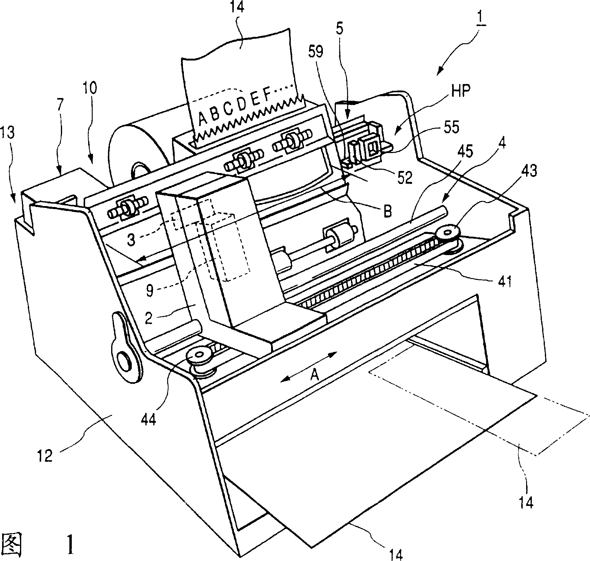
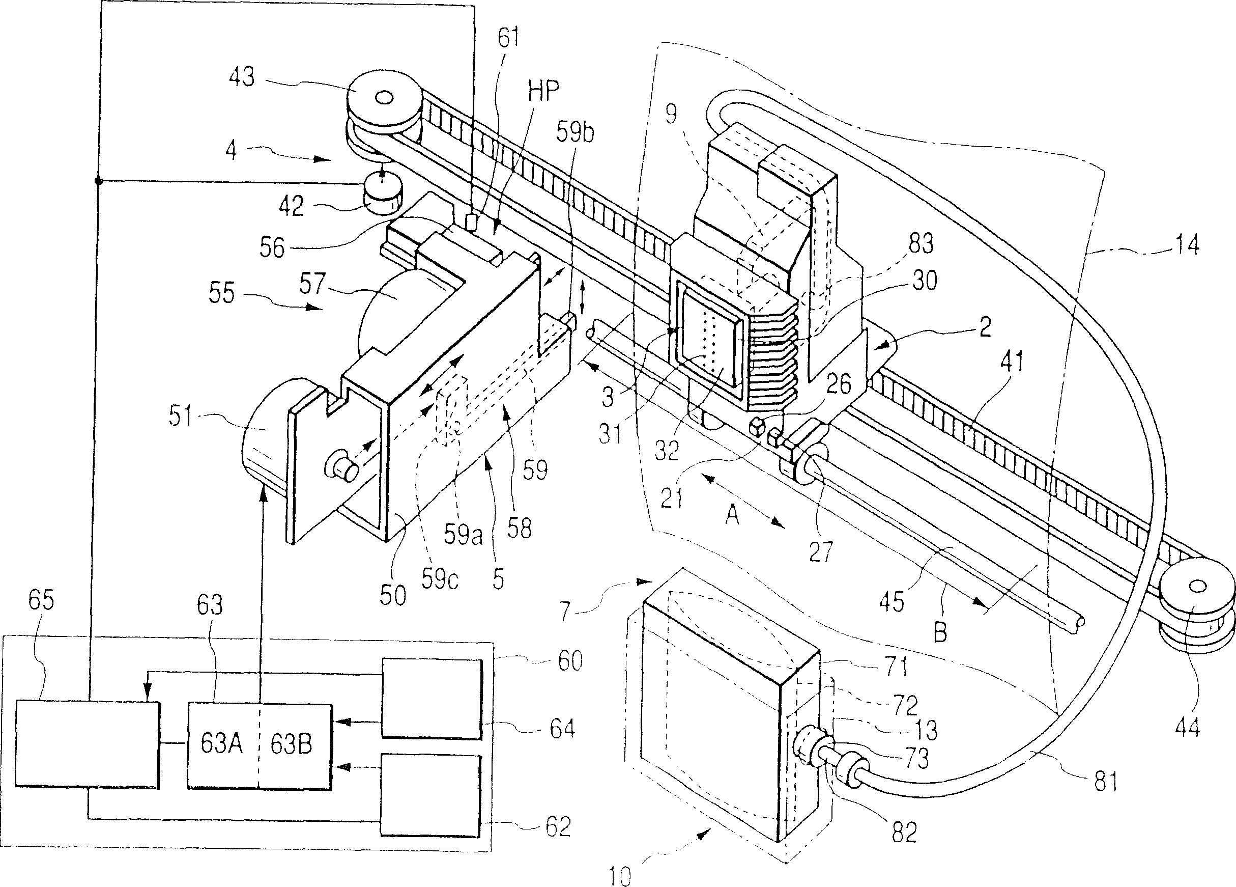
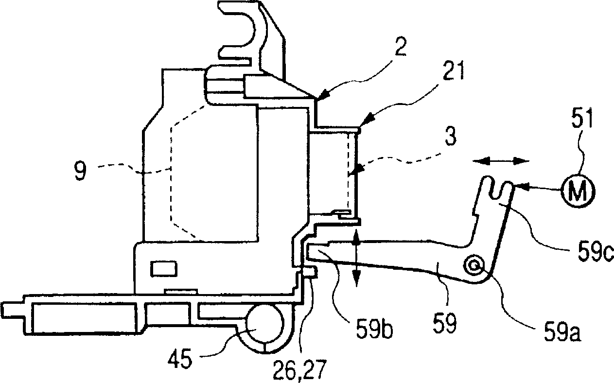
[0034] The inkjet recording apparatus 1 has a recording head 3 for ejecting ink droplets, and a carriage 2 carrying the recording head 3, a carriage drive mechanism 4 that drives the carriage 2 in the scanning direction shown by arrow A, and An ink supply mechanism 10 for supplying ink to the recording head 3 . The recording head 3 has a nozzle forming surface 32 on which a plurality of nozzles 31 for ejecting ink droplets are provided. The nozzle forming surface 32 is exposed outside the rectangular opening 30 on the carriage 2 .

[0035] Such as figure 2 As shown, the carriage drive mechanism 4 includes a guide rod 45 , a timing belt 41 stretched between the driving pulley 43 and the driven pulley 44 , and a carriage motor 42 for rotationally driving the driving pulley 43 . The lower side of the carriage 2 is slidably supported on the guide rod 45 and connected with the speed regulating belt 41 . When the timing belt 41 is driven by the carriage motor 42 , the carriage 2 ...


PUM


Abstract

The invention provides a method and apparatus for an ink jet recording apparatus in which a carriage lock is provided. When a return of the carriage to the home position HP is detected, the waiting time at the home position HP is counted. When this waiting time has reached a predetermined time, a carriage lock is engaged. When the carriage lock is engaged immediately after the carriage returns to the home position HP, the frequency of the carriage lock is reduced, thus enhancing its durability. Further, there is no need of disengaging the carriage lock at a restart of the printing, thus improving responsiveness at the restart of the printing.

Description

technical field [0001] The invention relates to an inkjet recording device and method, in particular to an inkjet recording device with a carriage locking mechanism and a control method thereof. Background technique [0002] A typical inkjet recording apparatus has a recording head which is moved along recording paper by a carriage to eject ink droplets, thus printing on the recording paper. Often, during printing, the carriage is in a waiting state and is at an initial position away from the recording area. When the carriage carrying the recording head is in the print waiting state, it moves to a predetermined initial position outside the recording area, and waits for a print command at the initial position. [0003] Although the carriage drive mechanism uses a braking force to keep the carriage at its original position, external vibrations may cause the carriage to move toward the recording area while the carriage is waiting at the initial position. In addition, the carr...

Claims


Application Information

Patent Timeline
IPC IPC(8): B41J29/393B41J29/54
CPCB41J29/54B41J29/393
Inventor 岩谷聪西冈笃小林直树
Owner SEIKO EPSON CORP
Why Eureka
Try Eureka