
Tripping device for overcurrent breaker

A technology for tripping device and circuit breaker, applied in circuits, emergency protection devices, electrical components, etc., can solve the problems of reduced functional reliability, difficult manufacturing, complicated circuit breaker design, etc., and achieve the effect of reducing geometric size

Inactive Publication Date: 2004-08-25
FELTEN & GUILLEAUME AUSTRIA
View PDF0 Cites 0 Cited by
  • Summary
  • Abstract
  • Description
  • Claims
  • Application Information

AI Technical Summary

Problems solved by technology

All in all, it complicates the design of the disconnect switch considerably
and thus lead to reduced functional reliability and more difficult manufacturing

Method used


Image

  • Tripping device for overcurrent breaker
  • Tripping device for overcurrent breaker
  • Tripping device for overcurrent breaker

Examples


Embodiment Construction

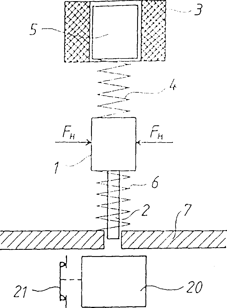
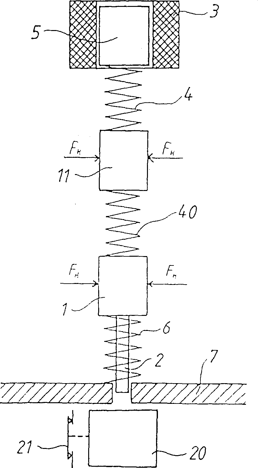
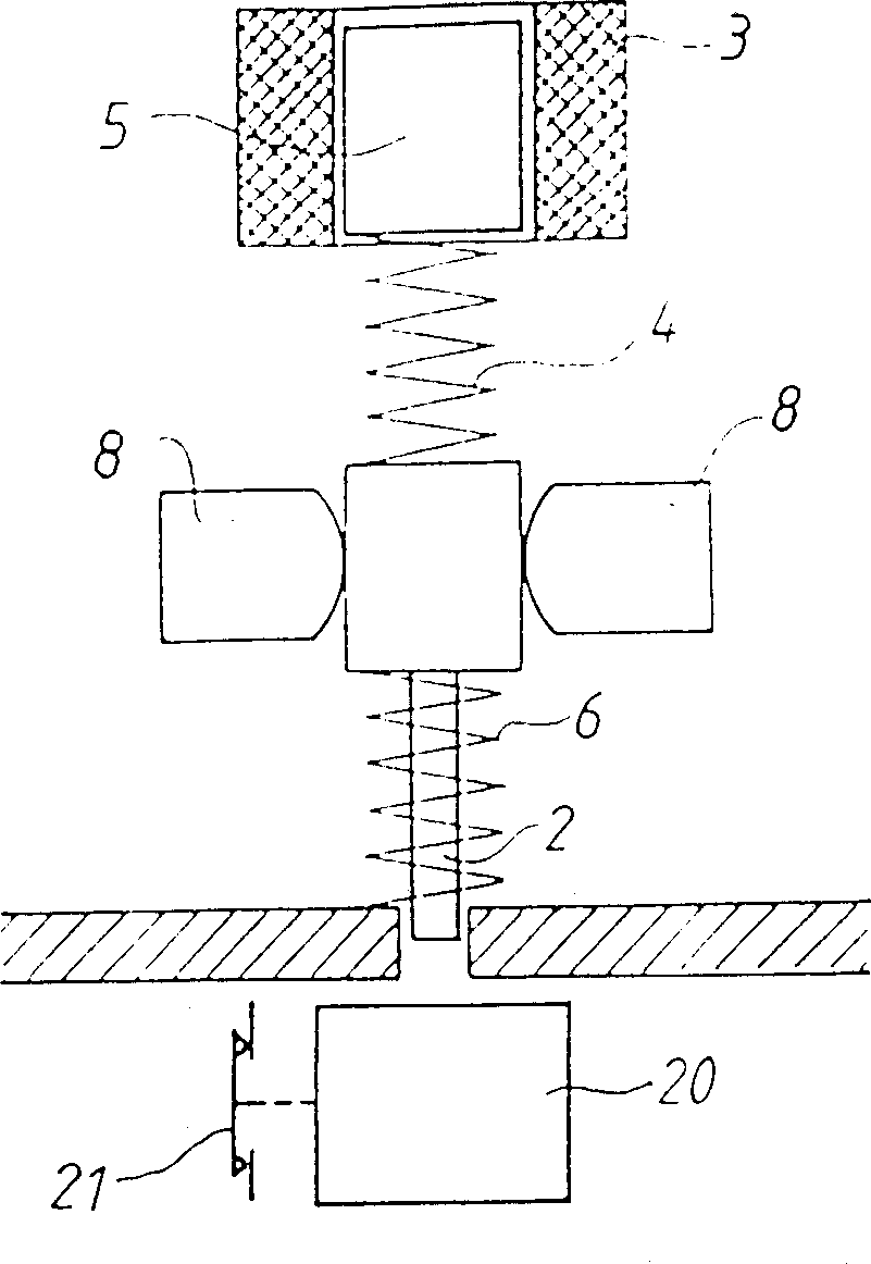
[0042] figure 1 The tripping device of the illustrated overcurrent circuit breaker, eg a circuit breaker, has an armature 5 made of a magnetic material, eg iron. The armature 5 can be moved directly by the coil 3 . The current flowing through coil 3 is actually the monitored current and may be disconnected. Furthermore, tripping the armature 1 can actuate a locking mechanism 20 which opens a contact 21 through which the monitored current flows. As shown, this action takes place by releasing the pin 2, which is integral with the trip armature, but as an alternative to this solution, it can also be provided directly by the trip armature 1 itself. accomplish.

[0043] The tripping armature 1 and the armature 5 are mechanically connected to each other by an elastic connecting element 4 which in its simplest form is a helical spring. The tripping armature 1 is installed so that it cannot move at will, but is controlled by the preset holding force F H remain in its resting posi...


PUM


Abstract

A releasing device of overcurrent circuit breaker such as circuit breaker, includes a release-armature (1) which actuates a switch lock (20). The armature (1) is actuated by a coil (3) through which the current to be monitored flows. The armature (1) is actuated by a magnetic armature (5) which is moved directly by the coil (3). The magnetic armature (5) is connected to the trigger armature (1) by means of at least on elastic coupling member (4) and preferably one or more auxiliary armatures (11). The trigger armature (1) is held in its rest position with a predetermined holding force, which is preferably a force generated in a mechanical manner.

Description

technical field [0001] The invention relates to a tripping device for an overcurrent circuit breaker, such as a circuit breaker. It consists of a tripping armature which controls the locking mechanism and is controlled by a coil through which the monitored current flows. Background technique [0002] Overcurrent circuit breakers mainly use fuse links on the one hand, which can only be used for a one-time breaking process, and on the other hand, automatic protection devices, which can be connected again and can therefore be used multiple times. [0003] In power systems, such overload protections as mentioned are usually provided in the supply line before it is divided into a plurality of circuits connected in parallel with each other. Each of these circuits has protective devices including personal protection (residual current devices or the like) and system protection (disconnectors, fuses, etc.). These circuits, for their part, can, if desired, be further subdivided into...

Claims


Application Information

Patent Timeline
Patent Type & Authority Patents(China)
IPC IPC(8): H01H71/24H01H71/26H01H71/32H01H71/44
CPCH01H71/2454H01H71/26H01H71/2463H01H71/32H01H71/44
Inventor 蒂博·波尔嘎
Owner FELTEN & GUILLEAUME AUSTRIA
Learn More