Arrangement for aiming a radio link antenna

A technology of radio link and line of sight, applied in the field of aiming antenna, can solve problems such as aiming error and variable measurement results, and achieve reliable aiming effect.

Inactive Publication Date: 2004-08-25
NOKIA SOLUTIONS & NETWORKS OY
View PDF1 Cites 0 Cited by
  • Summary
  • Abstract
  • Description
  • Claims
  • Application Information

AI Technical Summary

Problems solved by technology

Also, it should be noted that signals reflected from the surroundings affect the measured field, distorting the measurement results and causing aiming errors
[0007] Anothe

Method used


Image

  • Arrangement for aiming a radio link antenna
  • Arrangement for aiming a radio link antenna
  • Arrangement for aiming a radio link antenna

Examples


Embodiment Construction

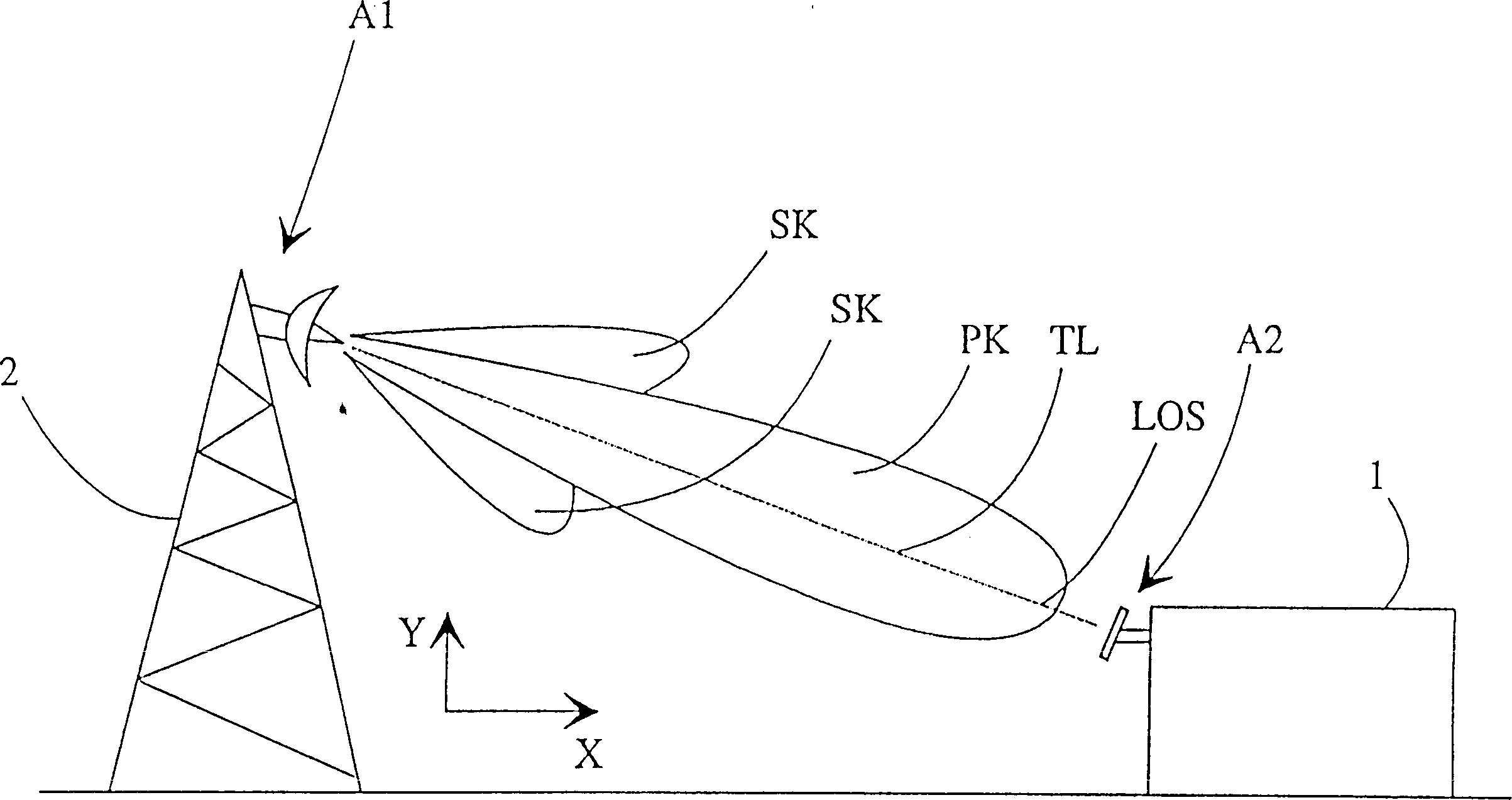
[0029] figure 1 The two radio link antennas A1 and A2 are shown aimed at their target, which in this example is the other antenna. figure 1 The main lobe PK of antenna 1 and its two side lobes SK are shown. The shape of the petals shown is seen from the side, ie along the vertical plane (arrow Y); it may be similar along the horizontal plane (arrow X), so that aiming takes place in both planes. In the illustrated example, the antenna A1 is mounted on the radio mast 2 and the antenna A2 is mounted on the wall of the building 1 . figure 1 Only the radiation pattern of antenna 1 is shown in , but antenna A2 also has a corresponding pattern. It is clear that the position and type of the antennas A1 and A2, as well as the shape and amount of the lobes PK, SK can also vary in different cases.

[0030] in addition, figure 1 A line of sight LOS between the antennas A1 and A2 is shown, which line of sight coincides with the direction of the main lobe and with the aiming direction, ...


PUM


Abstract

The invention relates to a method for aiming an antenna, in which method the antenna (A1, A2) is installed in a desired position in order to aim the antenna (A1, A2) at a target (A1, A2) for the reception, transmission or reception and transmission of radio signals. According to the invention, the direction (LOS) of the target (A1, A2) for selecting the position of the antenna (A1, A2) is determined using an optical sight (S, S1, S2, S3, S4, S5). Further according to the invention the sight (S, S1, S2, S3, S4, S5) is fitted in a predetermined position with respect to the position of the antenna (A1, A2) to be aimed, and the sight (S, S1, S2, S3, S4, S5) is aimed at the target (A1, A2) in order to determine at the same time the position of said antenna (A1, A2).

Description

technical field [0001] The invention relates to a method for aiming an antenna. The invention also relates to means for performing said aiming. Background technique [0002] The use of permanent and semi-permanent radio links is known to facilitate typical two-way radio connections. Radio links relay telephone and data communications and radio and television signals between stations. Radio links are implemented by electromagnetic radiation, ie radio waves, and the frequencies of radio waves in a radio link can range from radio frequency waves to microwave ranges. Links may be 40 to 50 kilometers long, with link masts typically 40 to 60 meters high. For example, a link antenna mounted on a mast may be a parabolic antenna. Typically there is a line-of-sight path between the linking antennas so that radio waves propagate unobstructed. [0003] A known radio transmission system for telephony and data communication is a cellular-based public land mobile network (PLMN), such ...

Claims


Application Information

Patent Timeline
IPC IPC(8): H01Q1/12H01Q3/08
CPCH01Q3/08H01Q1/125
Inventor 朱翰尼·珀斯黑莫
Owner NOKIA SOLUTIONS & NETWORKS OY
Why Eureka
Try Eureka