
Reel mechanism for fishing

A reel and reel technology, which is applied to fishing reels, applications, fishing, etc., can solve problems such as failure of action, lack of traction performance of traction braking mechanism, etc.

Inactive Publication Date: 2004-10-27
DAIWA SEIKO CORPORATION
View PDF2 Cites 0 Cited by
  • Summary
  • Abstract
  • Description
  • Claims
  • Application Information

AI Technical Summary

Problems solved by technology

[0008] Therefore, the problem in the prior art is that water intrudes into the reel, and the traction brake mechanism cannot obtain stable traction performance due to corrosion, resulting in malfunction.

Method used


Image

  • Reel mechanism for fishing
  • Reel mechanism for fishing
  • Reel mechanism for fishing

Examples


Embodiment Construction

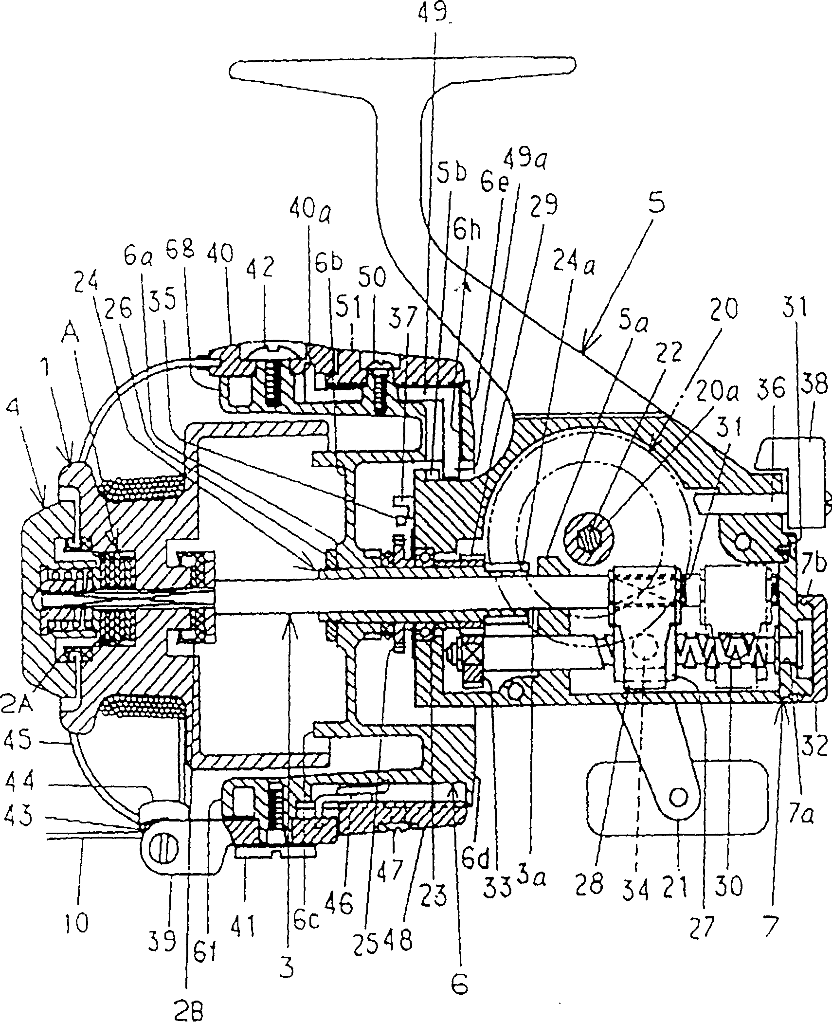
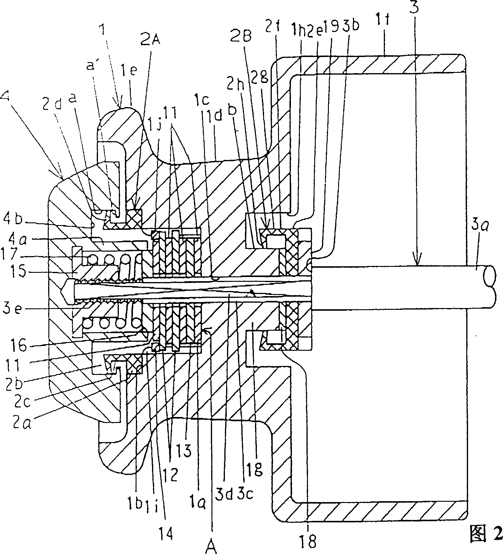
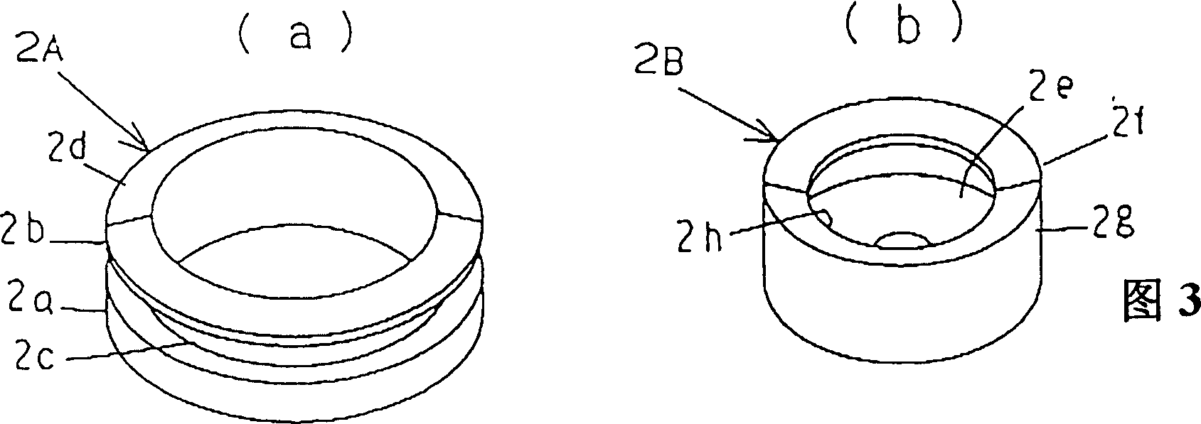
[0026] Next, the present invention will be described with reference to the illustrated embodiments. figure 1 Fig. 3 shows the first embodiment, figure 1 It is a sectional side view of the reel mechanism for fishing. Fig. 2 is an enlarged cross-sectional side view of key parts of facing members composed of bobbins. 3( a ) is a perspective view of the front waterproof sliding contact member, and FIG. 3( b ) is a perspective view of another waterproof sliding contact member on the rear side.

[0027] The first embodiment is a front pulling type fishing reel mechanism. The opposing member 1 composed of a reel has a deep concave portion 1a, a shallow concave portion 1b, a central through hole 1c, a fishing line winding portion 1d, and a front convex portion. An edge portion 1e, a rear large-diameter cylindrical portion 1f, a shaft cylindrical portion 1g, and a waterproof sliding contact portion 1h. The deep recess 1a is located in the center of the front. The shallow recess 1b ...


PUM


Abstract

A fishing spinning reel includes: a drag braking knob imparting a drag braking force to a spool, an opposite member opposite to the drag braking knob, a sliding contact section for waterproof arranged in one of the drag braking knob and the opposite member, and a sliding contact member for waterproof arranged in the other of the drag braking knob and the opposite member. The sliding contact member for waterproof includes a contact portion being elastically deformable and slidably contactable with a sliding surface of the sliding contact section for waterproof.

Description

technical field [0001] The present invention relates to a reel mechanism for fishing that can be waterproofed in the opposing member composed of a spool housing a traction braking mechanism, a spool body, and the like. Background technique [0002] In the spool of a conventional fishing reel mechanism, a through hole through which the spool shaft passes is formed at the center, and a recess for accommodating the traction brake mechanism is formed at the front side. On the spool shaft that passes through the through hole, a pull brake knob is mounted with a screw structure. [0003] Therefore, water may intrude from the front and rear sides of the spool, and the traction brake mechanism may not be able to obtain stable traction performance due to corrosion or the like, resulting in malfunction. [0004] In order to prevent troubles caused by water intrusion, in Japanese Patent Application Publication No. 3-67562 and Publication No. 3-91776, etc., it is proposed to implement ...

Claims


Application Information

Patent Timeline
IPC IPC(8): A01K89/01A01K89/027
CPCA01K89/0111A01K89/01A01K89/027A01K89/011221A01K89/029A01K89/03A01K89/015A01K89/019125A01K89/0183
Inventor 松田和之
Owner DAIWA SEIKO CORPORATION
Learn More