
Floating ship type water collecting trough with perforations

A technology of sump and pontoon, which is applied to the feeding/discharging device of settling tank, etc., can solve the problems of complex structure, heavy weight and high energy consumption.

Inactive Publication Date: 2004-11-24
罗志华
View PDF0 Cites 0 Cited by
  • Summary
  • Abstract
  • Description
  • Claims
  • Application Information

AI Technical Summary

Problems solved by technology

This structure, because the tank body is fixed, cannot be used in occasions that require intermittent water discharge and variable water level discharge
For this reason, there is also a supernatant liquid discharge device with a variable water level, which usually uses a motor to control the height of the water inlet to realize the top-down discharge of the supernatant liquid. Its structure is complex, heavy, and energy-consuming; there are also reports in A floating ball is added to the discharge device to keep it on the surface of the pool by using the buoyancy of the water. However, the buoyancy of the floating ball must be controlled by an air valve, which is difficult to control

Method used


Image

  • Floating ship type water collecting trough with perforations
  • Floating ship type water collecting trough with perforations
  • Floating ship type water collecting trough with perforations

Examples


Embodiment 1

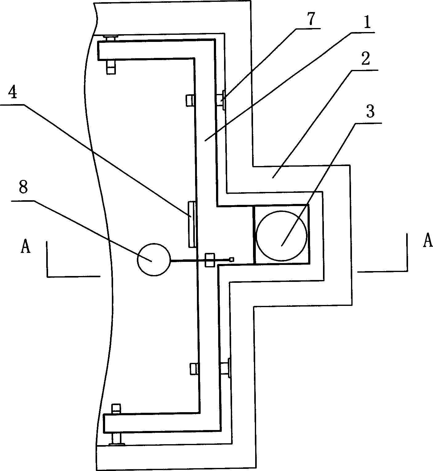
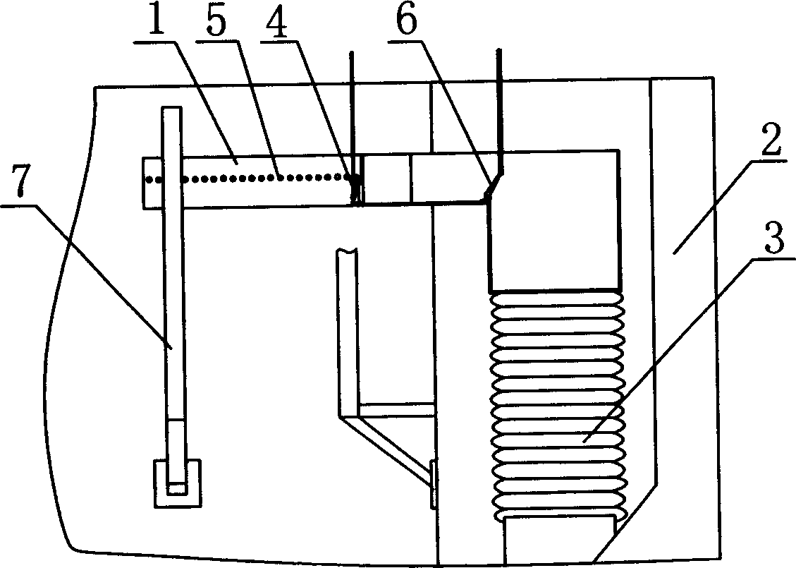
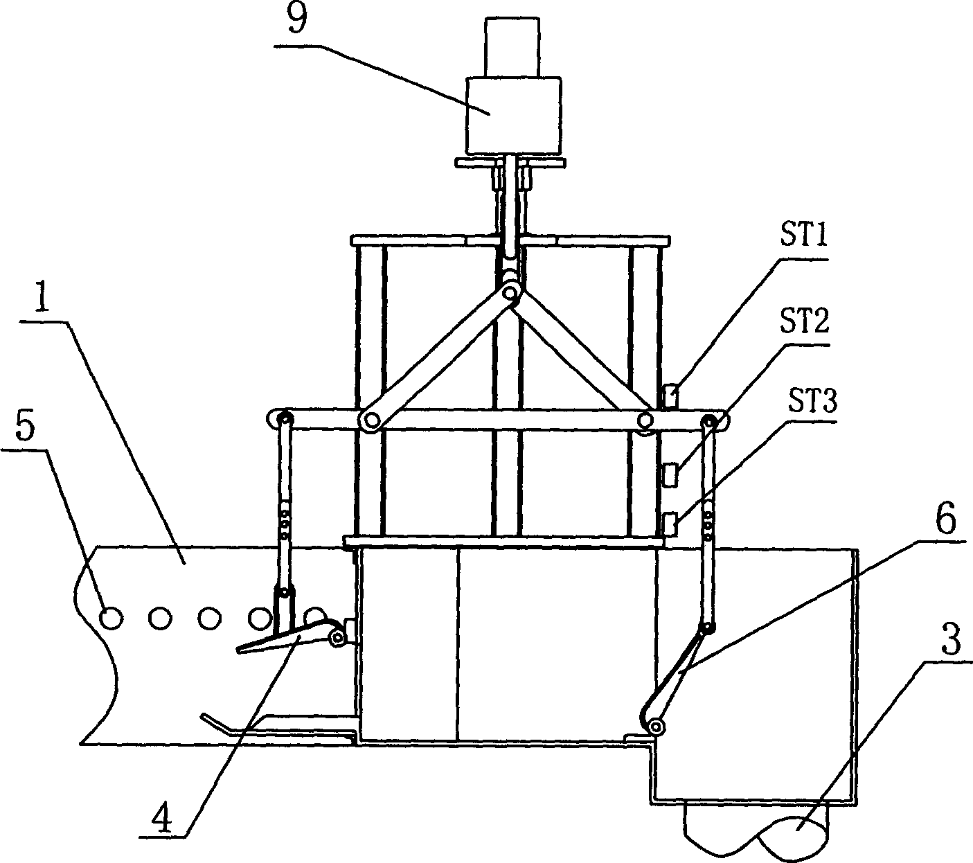
[0060] Embodiment one: see attached figure 1 To attach Figure 11 As shown, a floating boat-type perforated water collection tank includes a tank body 1 with a water collection hole 5 and a water outlet pipe 3. The water outlet pipe 3 communicates with the tank body 1. The top surface of the tank body 1 is open, and the water collection hole 5 Distributed on both sides of the tank body 1, a rotating weir plate adjustment structure is provided at the connection between the tank body 1 and the outlet pipe 3, the rotating shaft is located at the bottom of the tank body, and a water filling valve 4 that can be controlled to open and close is provided at the bottom of the tank body 1. The water filling valve 4 is a rotary valve, and the rotating shaft is located on the upper part of the valve; it also includes a control device that can drive the water level adjustment structure and the water filling valve. The control device makes the water collection tank have three states. In th...

Embodiment 2

[0080] Embodiment two: see attached Figure 12 As shown, a floating boat-type perforated water collection tank has the same basic structure as the embodiment, wherein the water level adjustment structure between the tank body and the outlet pipe adopts a lift-type weir plate adjustment structure, and the water retaining height of the weir plate increases when it rises. When descending, the water retaining height of the weir plate decreases.


PUM


Abstract

A float ship type perforated water collecting tank for discharging water in intermittent active sludge process, UNITANK technology and three-tank oxidizing ditch is composed of tank body with water collecting holes, water outlet tube, water level regulating structure between tank body and water outlet tube, water filling valve and control unit for driving said water level regulating structure and water filling valve. Its advantages are uniform water discharge and no need of power source.

Description

technical field [0001] The invention relates to a device used in a water treatment process, in particular to a collection device for supernatant in the precipitation process of water treatment. Background technique [0002] During the sedimentation process of sewage treatment, it is necessary to discharge the supernatant. At present, the common perforated sump is common. The clear liquid flows in from the water collecting hole and is discharged through the outlet pipe. This structure, because the tank body is fixed, cannot be used in occasions that require intermittent water discharge and variable water level discharge. For this reason, there is also a supernatant liquid discharge device with a variable water level, which usually uses a motor to control the height of the water inlet to realize the top-down discharge of the supernatant liquid. Its structure is complex, heavy, and energy-consuming; there are also reports in A floating ball is added ...

Claims


Application Information

Patent Timeline
Patent Type & Authority Patents(China)
IPC IPC(8): B01D21/24
Inventor 罗志华
Owner 罗志华
Learn More