Water activating device

A water heater and water inlet technology, which is applied in the field of water heaters, can solve problems such as poor negative ion effect, and achieve the effect of uniform water pressure and uniform water flow

Inactive Publication Date: 2005-08-03
GULESBAOYINTE
View PDF2 Cites 5 Cited by
  • Summary
  • Abstract
  • Description
  • Claims
  • Application Information

AI Technical Summary

Problems solved by technology

However, it is not possible to expect too much effect by adopting the form of a mechanism that moves the pallet 103 up and down as in Patent Document 1.
[0013] In addition, in the mechanism that pressurizes the ceramic balls in a close contact state to make them move slightly as in Patent Document 2, the effect of generating negative ions from calcium carbide such as calcium carbide is not good.

Method used


Image

  • Water activating device
  • Water activating device
  • Water activating device

Examples


Embodiment 1

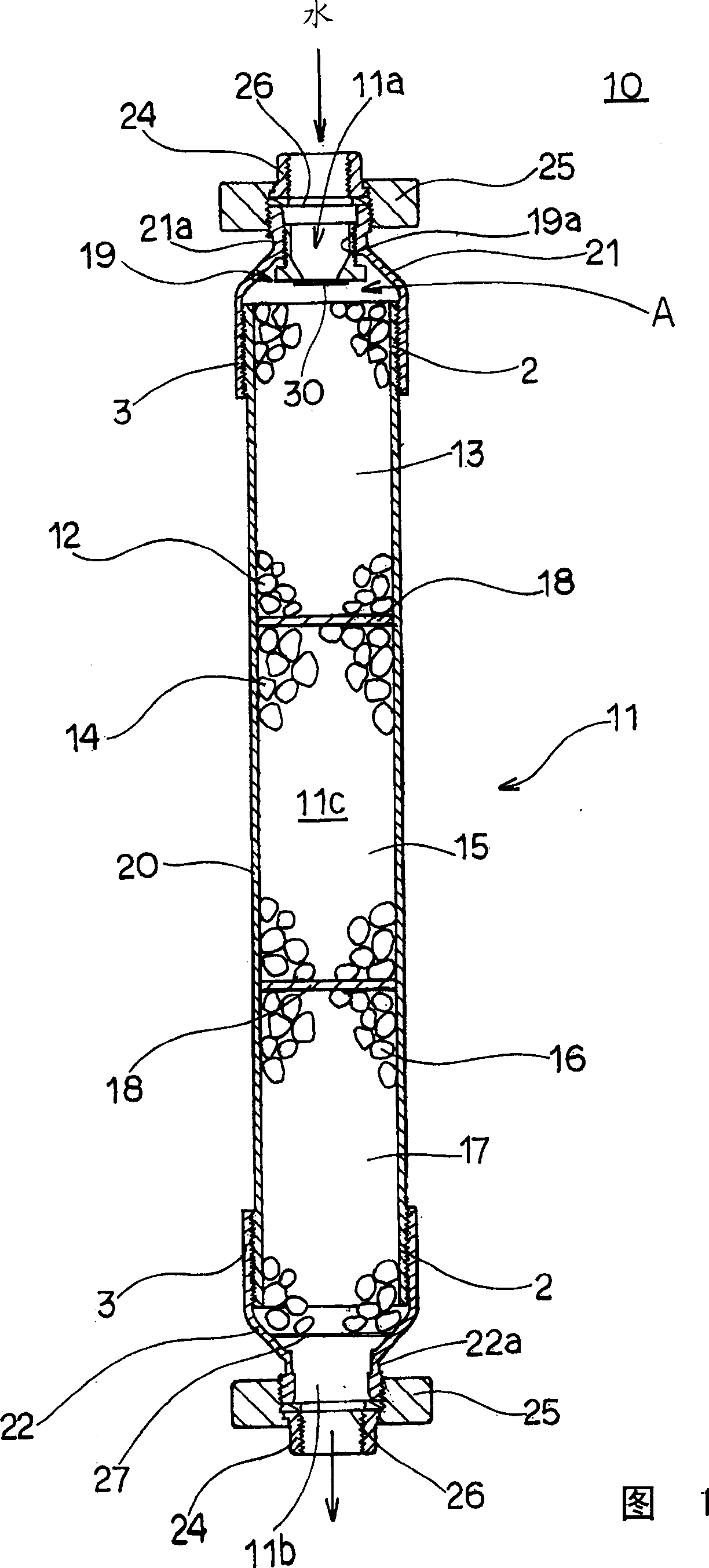
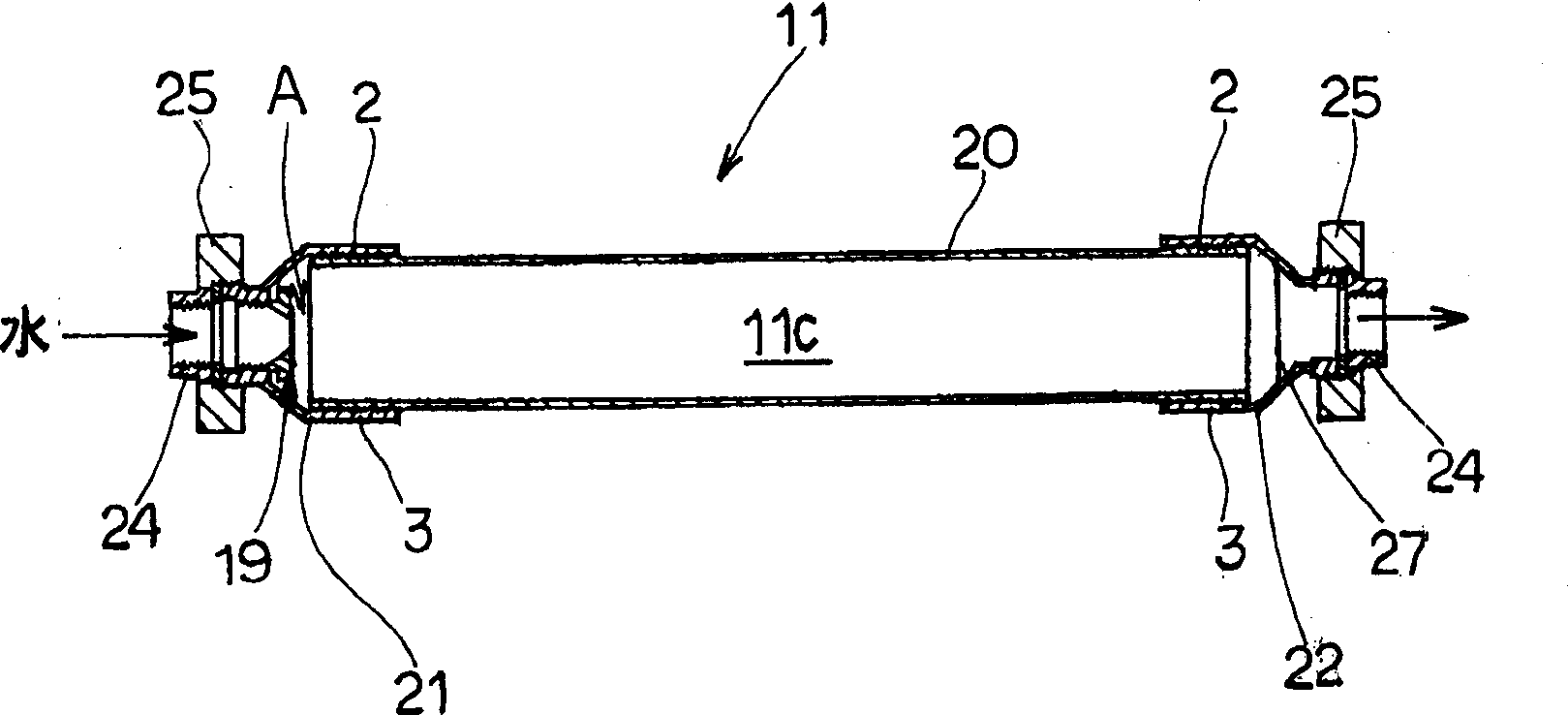
[0060] In Figure 1 and figure 2 Among them, 10 is the water living device of embodiment 1 of the present invention, and this water living device 10 has following structure: It has cylindrical shell 11, and this cylindrical shell 11 forms water inlet 11a at the upstream end of supplying the water to be activated, and discharges The downstream end of the activated water forms the water outlet 11b, and the inner space becomes the water flow passage 11c; on the water flow passage 11c, the anion chamber 13, the accommodating anion chamber 13 and the accommodating anion emitting ceramics 12 are arranged respectively in series along the longitudinal direction of the water flow passage 11c. The far-infrared chamber 15 of the far-infrared radiating ceramics 14, and the medical stone chamber 17 that accommodates the medical stone ceramics 16; these anion chambers 13, the far-infrared chamber 15 and the medical stone chamber 17 are separated by a water-permeable separating plate 18 respe...


PUM


Abstract

The invention provides a water activator which radiates a large quantity of anions and far-infrared rays and refines water containing a mount of mineral component. Three chambers (13, 15, 17) in vertical series on water stream (11c) are obtained by dividing a cylindrical body (11) of the water activator (10) and a corresponding anion radiation ceramics 12, far-infrared radiation ceramics 14 and medical stone ceramics 16 are accommodated in the case body 1, so that the anion and far infrared ray can be radiated to the water on the water stream (11c) and the mineral component can be digested. Thus the active water of high quality can be refined.

Description

technical field [0001] The present invention relates to a water activator, in particular to a water activator in which ceramic balls are collided with each other by water flow in a cylindrical shell, thereby ionizing and activating the water to improve water quality. technical background [0002] Conventionally, the water spring of patent document 1 which fills a cylindrical case with ceramic balls and activates the tap water supplied into a cylindrical case with ceramic balls, thereby improving the water quality of tap water was announced. [0003] Such as Figure 10 As shown, the water heater of Patent Document 1 has such a structure that in the inner space of a casing (cylindrical casing) 101 arranged longitudinally, there are spaced apart from each other in the axial direction (longitudinal direction) of the casing 101 and are movable in the axial direction. A plurality of pallets (separation plates) 103 each having a plurality of through holes 102 formed therein is acco...

Claims


Application Information

Patent Timeline
Patent Type & Authority Applications(China)
IPC IPC(8): C02F1/30C02F1/00C02F1/68
Inventor 石桥利广
Owner GULESBAOYINTE
Why Eureka
Try Eureka