Supercharge Your Innovation With Domain-Expert AI Agents!

Electro-optical switching method and structure for regulating Q in cavity

An electro-optic and beam technology, applied in the application field of laser technology, can solve problems such as difficulty in obtaining laser beams

Inactive Publication Date: 2005-02-09
ANHUI INST OF OPTICS & FINE MECHANICS - CHINESE ACAD OF SCI
View PDF0 Cites 0 Cited by
  • Summary
  • Abstract
  • Description
  • Claims
  • Application Information

AI Technical Summary

Problems solved by technology

This structure can only have the change of the Q value in the cavity of one resonant cavity, and it is difficult to obtain a laser beam with multiple pulses and multiple wavelengths of the same beam

Method used


Image

  • Electro-optical switching method and structure for regulating Q in cavity
  • Electro-optical switching method and structure for regulating Q in cavity
  • Electro-optical switching method and structure for regulating Q in cavity

Examples


Embodiment Construction

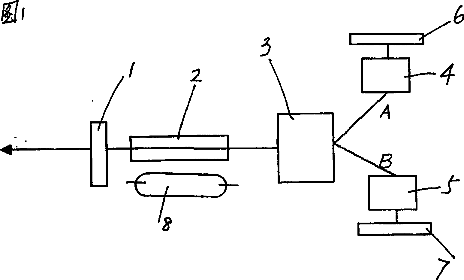
[0012] Taking the intracavity Q-switched electro-optic switch as the working state 1 as an example, other states are similar.

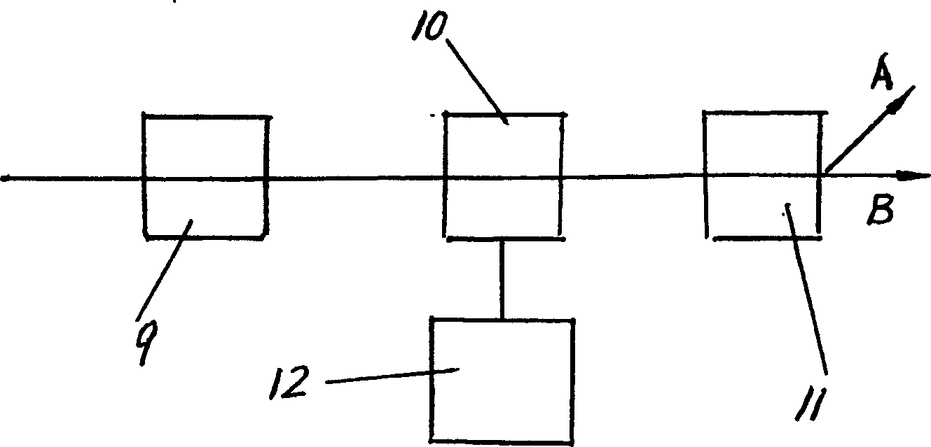
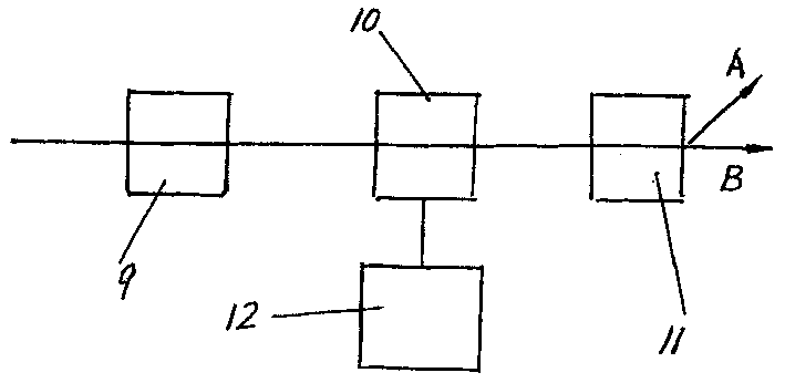
[0013] See Figures 1 and 2, where 1, front cavity mirror, 2, tunable laser crystal, 3, intracavity Q-switched electro-optic switcher, 4, 5 tuning element, 6, 7 rear cavity mirror, 8, flash lamp, 9, bias Starter, 10 Q-switching crystal, 11, polarization beam splitter, 12, electric control system of Q-switching crystal, A direction and B direction are respectively the beam transmission directions after splitting whose polarization directions are perpendicular to each other.

[0014] The invention is used in a double-wavelength double-pulse laser with the same beam. This system consists of front cavity mirror 1, laser crystal 2, polarizer 9, Q-switching crystal 10, polarization beam splitter 11, two sets of tuning elements 4, 5, rear cavity mirrors 6, 7 and Q-switching from left to right. The electronic control system 12 of the crystal and the flashligh...


PUM


Abstract

An in-cavity Q-regulating photo-electric switching device used for same beam multi-pulse laser, same-beam multi-pulse multi-wavelength laser, pollution measuring radar, dual-wavelength homography, spectrofluorescence diagnosis, satellite range finding, etc is composed of polarizer, Q-regulating crystal, polarized splitter and electric control system of Q-regulating crystal. Under the control of said control system, the Q-regulating crystal can respectively generate 1 / 4-wave, O-wave and 1 / 2-wave voltages, whose time sequence and waveforms can be controlled to obtain the transmission characteristics of particularly combined beam in directions A and B.

Description

technical field [0001] The invention relates to the application field of laser technology, in particular to a method and structure of an intracavity Q-switched electro-optic switcher. Background technique [0002] At present, the typical intracavity Q-switching technology is composed of the rear cavity mirror of the resonator, the Q-switching crystal, the polarizer, and the electronic control system of the Q-switching crystal. If the fluorescence emission of the laser crystal has good polarization characteristics, the polarization device can be omitted. During operation, the voltage change on the Q-switched crystal is used to control the change of the Q value of the laser to obtain the Q-switched laser output. This structure can only have the change of the Q value in the cavity of one resonant cavity, and it is difficult to obtain a laser beam with multiple pulses and multiple wavelengths in the same beam. Contents of the invention [0003] The object of the present inve...

Claims


Application Information

Patent Timeline
Patent Type & Authority Patents(China)
IPC IPC(8): H01S3/092H01S3/127H01S3/16
Inventor 陈长水
Owner ANHUI INST OF OPTICS & FINE MECHANICS - CHINESE ACAD OF SCI
Features
  • R&D
  • Intellectual Property
  • Life Sciences
  • Materials
  • Tech Scout
  • Unparalleled Data Quality
  • Higher Quality Content
  • 60% Fewer Hallucinations
Learn More