Electronic device with improved heat dissipation performance

A technology for electronic devices and heat sinks, applied in circuits, electrical components, indirect heat exchangers, etc., to solve problems such as fan noise, space limitations occupied by heat sinks, and heat dissipation methods limitations

Inactive Publication Date: 2005-05-25
SONY CORP
View PDF0 Cites 1 Cited by
  • Summary
  • Abstract
  • Description
  • Claims
  • Application Information

AI Technical Summary

Problems solved by technology

[0006] However, heat dissipation methods that rely on natural heat radiation through the heat sink are also limited due to the space occupied by the he

Method used


Image

  • Electronic device with improved heat dissipation performance
  • Electronic device with improved heat dissipation performance
  • Electronic device with improved heat dissipation performance

Examples


Embodiment Construction

[0030] Preferred embodiments of the present invention are described below with reference to the accompanying drawings. However, it should be understood that the embodiments shown below are not the only ones, and for the convenience of description, only various specifically shown technical methods are introduced, unless otherwise specified.

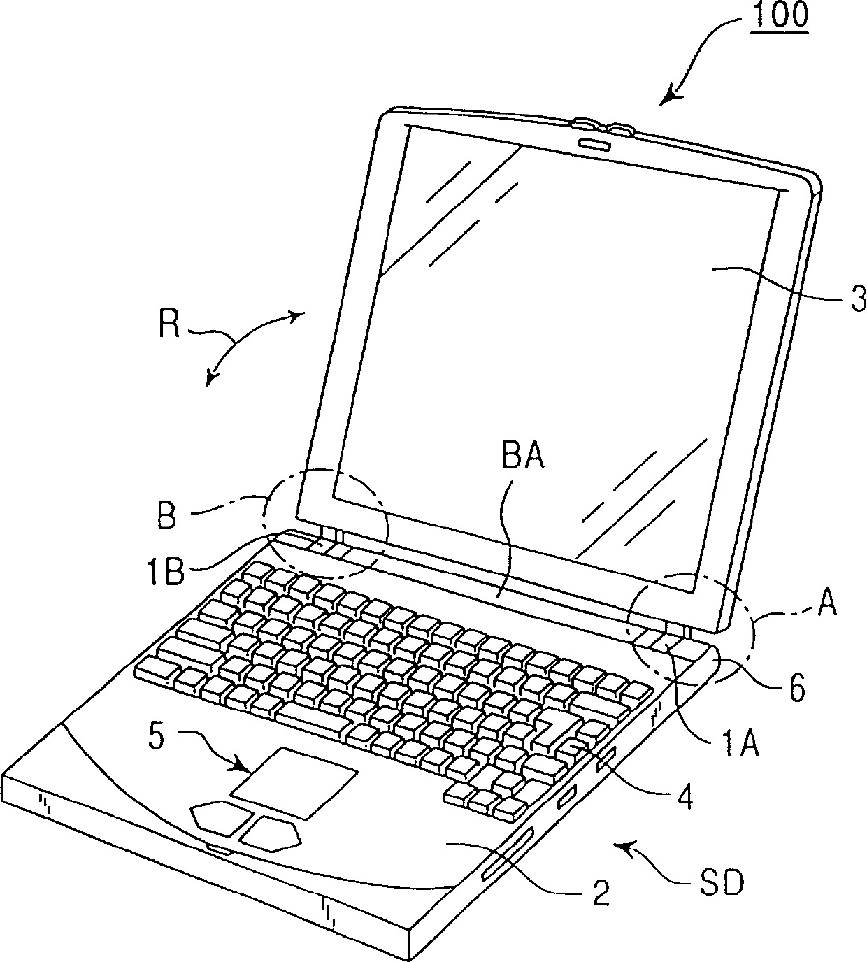
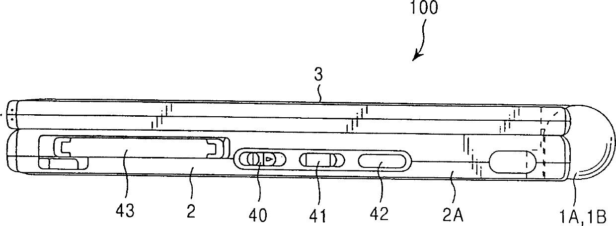
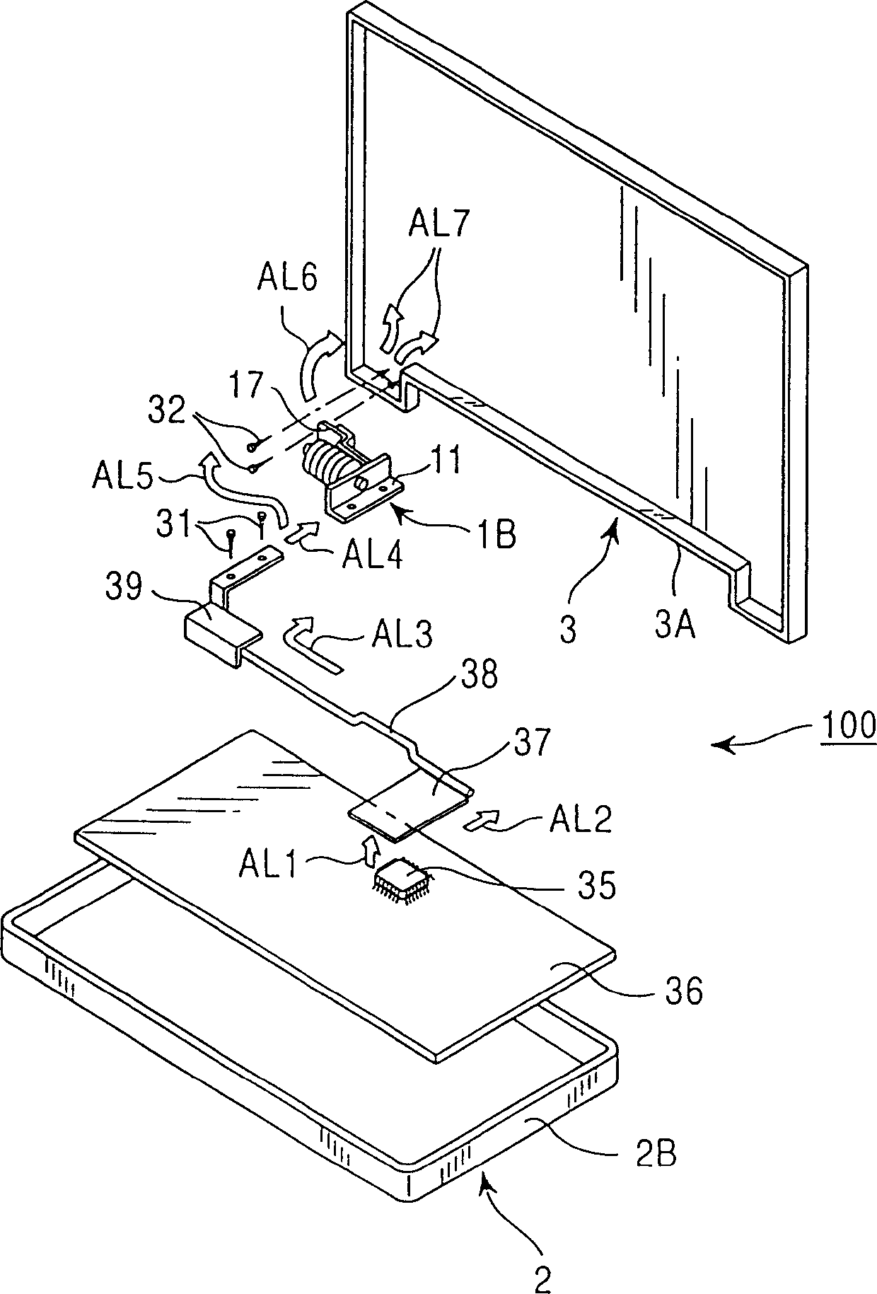
[0031] Referring to FIG. 1 , a portable computer with a unique hinge structure is indicated by 100 as an embodiment of the electronic device of the present invention. The portable computer 100 includes a main body unit 2 , a display unit 3 , a keyboard 4 , hinges 1A, 1B delimited by dot-dash circles, and the like.

[0032] In addition to the keyboard 4, the main body unit 2 and the pointing device 5 each have various elements and circuits. The display unit 3 may be a liquid crystal display (reference denoted as "LCD"). One end of the display unit 3 is pivotally connected or hinged to the adjacent end of the main unit 2 through hinges 1A,...


PUM


Abstract

A portable electronic device such as a portable personal computer has a first part such as a main body unit equipped with a heat generating element such as a CPU; a second part such as a display unit; and a connector for pivotally connecting the first and second parts. The connector includes a hinge that provides a mechanical connection between the first and second parts while conducting heat from a heat generating element within the first part to the second part so that the heat is dissipated from the second part. The electronic device has improved heat dissipation without having to have a larger size.

Description

technical field [0001] The present invention relates to an electronic device, particularly an electronic device such as a portable computer. Background technique [0002] Various types of portable electronic devices, such as portable computers, including electronic devices incorporating central processing units (CPUs), are currently commercially available. Such electronic devices primarily consume electrical power and thus generate heat that must be dissipated. [0003] Certain types of portable electronic devices such as portable computers have a basic structure consisting of a main body unit and a display unit hinged to the main body unit. This basic structure is commonly used in notebook personal computers (PCs) of the A-4 type and small notebook PCs such as the B-5 type. [0004] The hinges described above are generally mechanical hinges having a stationary part and a movable part pivotally mechanically connected to the stationary part. When a certain torque is applie...

Claims


Application Information

Patent Timeline
IPC IPC(8): F28D15/02G06F1/20H01L23/427H05K7/20
CPCG06F1/203G06F1/1616
Inventor 棚桥诚浅轮勉市川满
Owner SONY CORP
Why Eureka
Try Eureka