
Card connector

A technology of card connectors and electrical connectors, which is applied in the direction of connecting and connecting parts of devices, instruments, etc., and can solve the problems of not being able to install the discharge rod 124, violating miniaturization, increasing the number of parts, etc.

Inactive Publication Date: 2005-08-24
TYCO ELECTRONICS JAPAN GK
View PDF1 Cites 0 Cited by
  • Summary
  • Abstract
  • Description
  • Claims
  • Application Information

AI Technical Summary

Problems solved by technology

For example, if Figure 12 As shown, even if it is intended to install the discharge rod 124 provided on the right side wall of the upper side case 121 or the lower side case 122 to the other left side wall, since no discharge rod is installed on the left side wall 124, so that the discharge rod 124 cannot be installed on the left side wall
In order to be able to install the discharge rod 124 provided on the right side wall of the upper side case 121 or the lower side case 122 on the left side wall of the other, a hole for mounting the discharge rod 124 is provided on the left side wall. When installing components, since the installation components for installing the discharge rod 124 remain on the right side wall, the lateral width of the housing assembly 120 will be increased, which violates the requirement of miniaturization.
[0010] On the other hand, in order to be able to install the discharge rod 124 on the right side wall of the upper side housing 121 or the lower side housing 122 on the other left side wall, a device for installing the discharge rod 124 is provided on the left side wall. While eliminating the installation member on the right side wall, another housing different from the existing housings 121 and 122 is required, which increases the number of parts
[0011] In addition, since in order to mount the card connector 100 on the circuit board PCB, the entire body of the card connector 100 in which the housing assembly 120 with the discharge mechanism is mounted on the end plate 110 is mounted on the circuit board PCB, After the electrical connector 112 of the end plate 110 is soldered and connected to the conductive base on the circuit substrate PCB, there is a problem that the housing assembly 120 equipped with the discharge mechanism cannot be easily exchanged.

Method used


Image

  • Card connector
  • Card connector
  • Card connector

Examples


Embodiment Construction

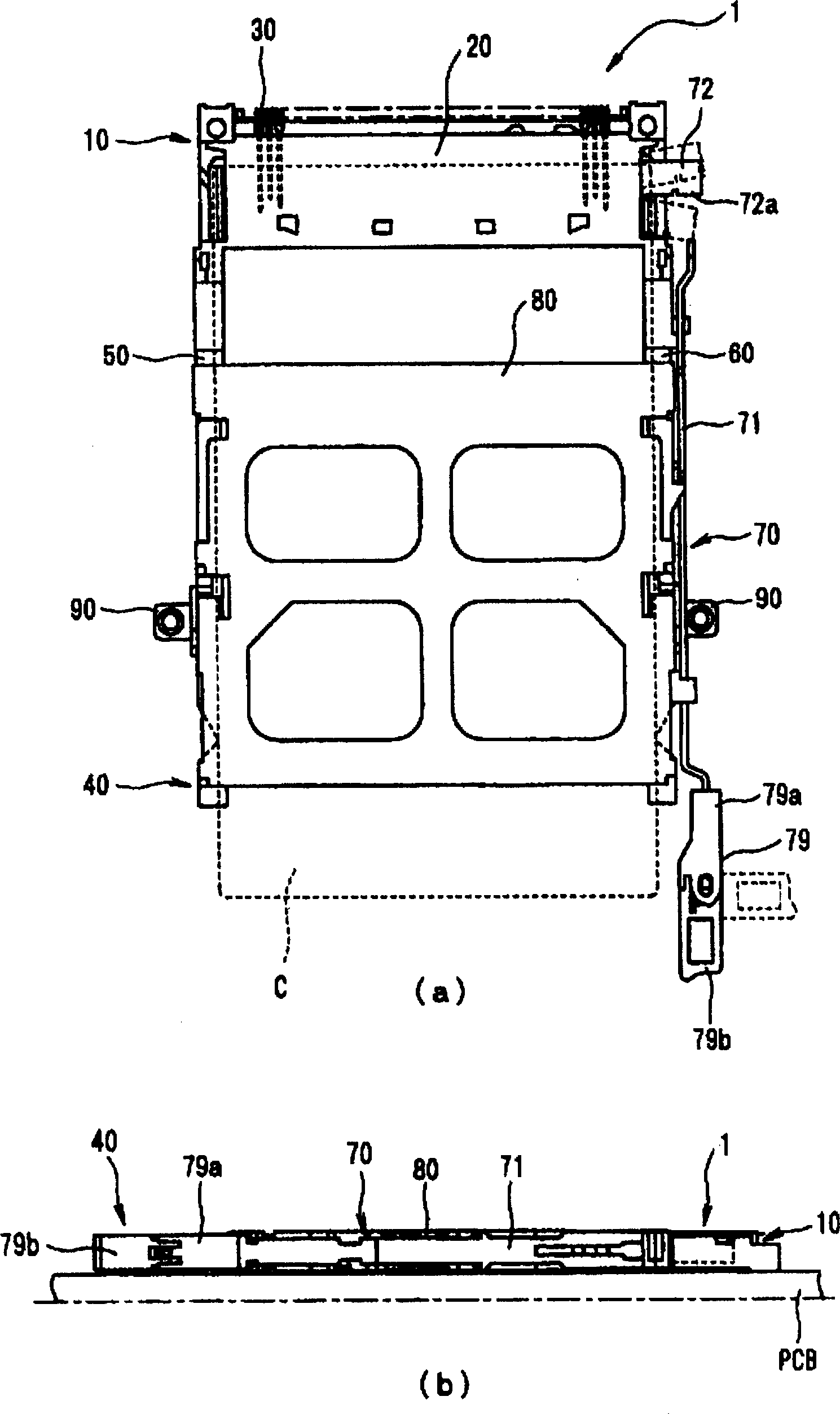
[0030] Embodiments of the present invention will be described below with reference to the drawings. figure 1 The card connector according to the present invention is shown, (a) being a plan view thereof, and (b) being a right side view thereof.

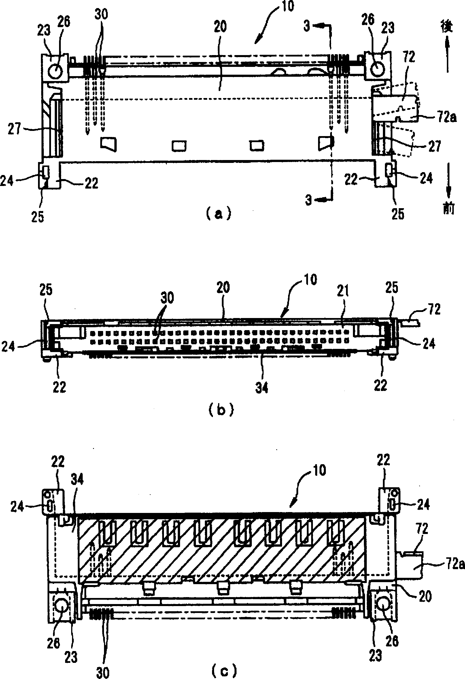
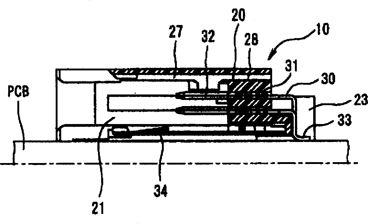
[0031] exist figure 1 Among them, the card connector 1 is composed of an end plate 10 mounted on a circuit board PCB, and a frame assembly 40 equipped with a discharge mechanism mounted on the circuit board PCB while being assembled on the end plate 10 . Simultaneously, card connector 1 is housed by the rear side of frame assembly 40 of discharge mechanism ( figure 1 The lower side in (a) receives a card C such as a memory card, a credit card, or an HDD card, and electrically connects the card C to the circuit board PCB. In addition, the card C is ejected to the outside by the ejection mechanism 70 provided on the frame assembly 40 equipped with the ejection mechanism. The ejection mechanism 70 includes an ejector lever 71 with ...


PUM


Abstract

The card connector 1 has card-guiding grooves 53 and 63 that are used to accommodate and guide a card C on the left and right sides of an insulating housing 20. An ejection bar 71 is attachable to either left or right guide arms 50 and 60. The left and right guide arms 50 and 60 are formed with symmetrical structures so that they are interchangeable between the left and right sides. Furthermore, the frame 80 that connects the left and right guide arms 50 and 60 to each other and the brackets 90 that are used to attach the left and right guide arms 50 and 60 to the circuit board are each constructed so that they can be mounted on the left and right guide arms 50 and 60 from above or below.

Description

technical field [0001] The present invention relates to a card connector for electrically connecting a card such as a memory card, a credit card, or an HDD card to a circuit board, and more particularly to a card connector having an ejection mechanism for ejecting the card. Background technique [0002] Conventionally, card connectors equipped with an ejection mechanism for electrically connecting cards such as memory cards, credit cards, and HDD cards to circuit boards have been used in laptop computers, notebook computers, and the like. [0003] As such a card connector equipped with an ejection mechanism, for example, known Figure 12 The product shown (see JP-A-11-119861). [0004] This card connector 100 equipped with a discharge mechanism consists of an end plate 110 mounted on a circuit substrate PCB, a plurality of electrical contacts 112 assembled in an insulating box 111, and a shell equipped with a discharge mechanism assembled on the end plate 110. body assembly...

Claims


Application Information

Patent Timeline
IPC IPC(8): G06K17/00G06K13/08H01R12/30H01R13/635
CPCG06K13/08G06K13/0825G06K13/0806H01R12/71H01R13/62
Inventor 桥本信一
Owner TYCO ELECTRONICS JAPAN GK
Learn More