

Z-shaped multiplexer for wavelength divisions
A technology of wavelength division and multiplexer, which is applied in the direction of instrument, optical waveguide coupling, light guide, etc., can solve the problems of frequency band center wavelength shift and optical loss, etc., and achieve the effect of reducing frequency band center wavelength shift and reducing optical loss
- Summary
- Abstract
- Description
- Claims
- Application Information
AI Technical Summary
Problems solved by technology
Method used
Image

Examples
Embodiment Construction
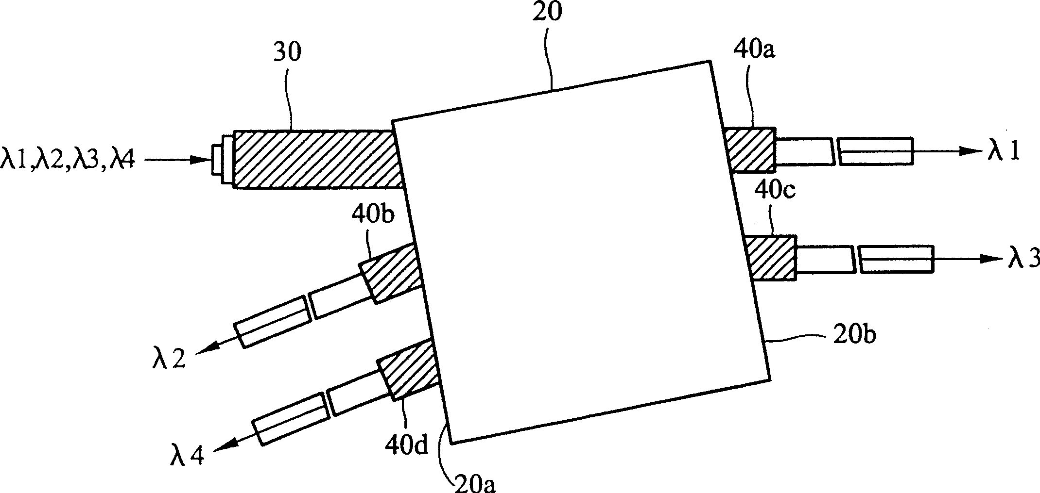
[0022] figure 2 It is the top view of the zigzag wavelength division multiplexer of the present invention. like figure 2 As shown, the zigzag wavelength division multiplexer of the present invention includes an intermediate block (intermediate block) 20, an input end 30 and a plurality of output ends 40a, 40b, 40c, 40d; wherein the input end 30 and the plurality of output ends 40a , 40b, 40c, 40d are arranged on the two sides 20a, 20b of the middle block 20 respectively. After a multi-channel beam (multi-channel light) enters the middle block 20 from the input end 30, a first-channel beam (first-channel beam) λ1 is output through a first output end 40a, and a second output end 40b outputs a second-channel beam (second-channel beam) λ2, outputs a third-channel beam (third-channel beam) λ3 through a third output terminal 40c, and outputs a remaining waveband beam through a fourth output terminal 40d (residual-channel beam) λ4.
[0023] Figure 3A is a perspective view of ...
PUM
| Property | Measurement | Unit |
|---|---|---|
| angle of incidence | aaaaa | aaaaa |
Abstract
Description
Claims
Application Information