Method and device for box spinning

A technology of centrifugal spinning and spinning machines, which is applied to spinning machines, textiles, papermaking, and open-end spinning machines, etc., and can solve problems such as the generation and existence of yarn package residues that cannot be found, and can only be found at a later date

Inactive Publication Date: 2005-11-02
OERLIKON TEXTILE GMBH & CO KG
View PDF5 Cites 2 Cited by
  • Summary
  • Abstract
  • Description
  • Claims
  • Application Information

AI Technical Summary

Problems solved by technology

Although it is possible to reliably remove the yarn package remnants by such a device, the generation and existence of such yarn package remnants often cannot be found or can be found very late.

Method used


Image

  • Method and device for box spinning
  • Method and device for box spinning
  • Method and device for box spinning

Examples


Embodiment Construction

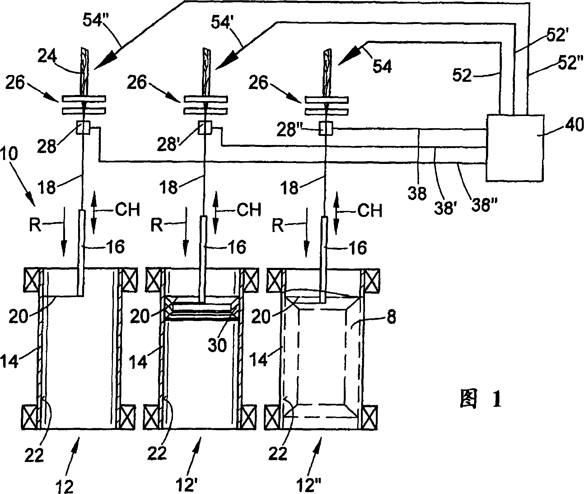
[0040]Fig. 1 shows schematically a centrifugal spinning machine 10 with many working positions 12, and three such working positions 12, 12' and 12 " are shown in sectional view in Fig. 1 .

[0041] Each working station 12 comprises a centrifugal spinning pot 14 rotating at high speed supported, for example, by magnetic bearings not shown.

[0042] The centrifugal spinning tanks 14 are each associated with a tubular yarn guide 16 capable of traversing and descending in the direction R, the longitudinal axis of which is located on the axis of rotation of the centrifugal spinning tank 14 .

[0043] The individual rovings 24 are fed into the centrifugal spinning tank 14 via the yarn feeder 16 and are placed as yarn cake 8 on the inner wall 22 of the spinning centrifugal tank 14 with the formation of a yarn strand 20 . A spun yarn 18 can thus be produced from the roving by the rotation of the centrifuge pot 14 .

[0044] The roving 24 is drafted in a drafting device 26, which is o...


PUM


Abstract

The invention relates to a method and device for operating a pot spinning machine which has a plurality of identical work stations each having a drafting device with a slubbing stop device, a spinning centrifuge rotating at high speed around an axis, and a tubular reciprocable guide. A slubbing emerging from the yarn guide mouth forms a rotating yarn leg which is deposited on the inner wall of the spinning centrifuge in the form of a spinning cake. At the start of a spinning cycle of the spinning machine (10), the individual spinning centrifuges (14) of the spinning machine are checked for the presence (30) of yarn cake remnants.

Description

technical field [0001] The invention relates to a method for centrifugal spinning and a device for centrifugal spinning. Background technique [0002] In centrifugal spinning, a sliver placed in a can or an initial roving (also called roving) that is drawn in a drafting device, such as a sliver placed in a can, is The yarn guide is fed into a rotating centrifugal spinning tank to be spun into yarn, and is placed on the inner wall of the centrifugal spinning tank to form a so-called yarn cake. [0003] That is, the roving output from the outlet of the yarn guide is conveyed to the inner wall of the centrifugal spinning tank under the influence of the airflow rotating with the centrifugal spinning tank, thereby producing a yarn strand rotating around the centrifugal axis. Through the rotation of this strand, the yarn being produced acquires the desired twist before being placed on the inner surface of the centrifuge tank to form a cake. After a period of spinning process, or...

Claims


Application Information

Patent Timeline
Patent Type & Authority Patents(China)
IPC IPC(8): D01H1/08D01H1/36D01H4/04D01H7/74D01H9/06D01H13/14D01H13/16D01H13/32
CPCD01H13/16D01H1/08
Inventor K·科尔特策
Owner OERLIKON TEXTILE GMBH & CO KG
Why Eureka
Try Eureka