

Air filter and blower therewith
A technology of air filter and air supply device, applied in the directions of dispersed particle filtration, space heating and ventilation, space heating and ventilation details, etc., to achieve the effect of less dust removal
- Summary
- Abstract
- Description
- Claims
- Application Information
AI Technical Summary
Problems solved by technology
Method used
Image

Examples
Embodiment approach 1
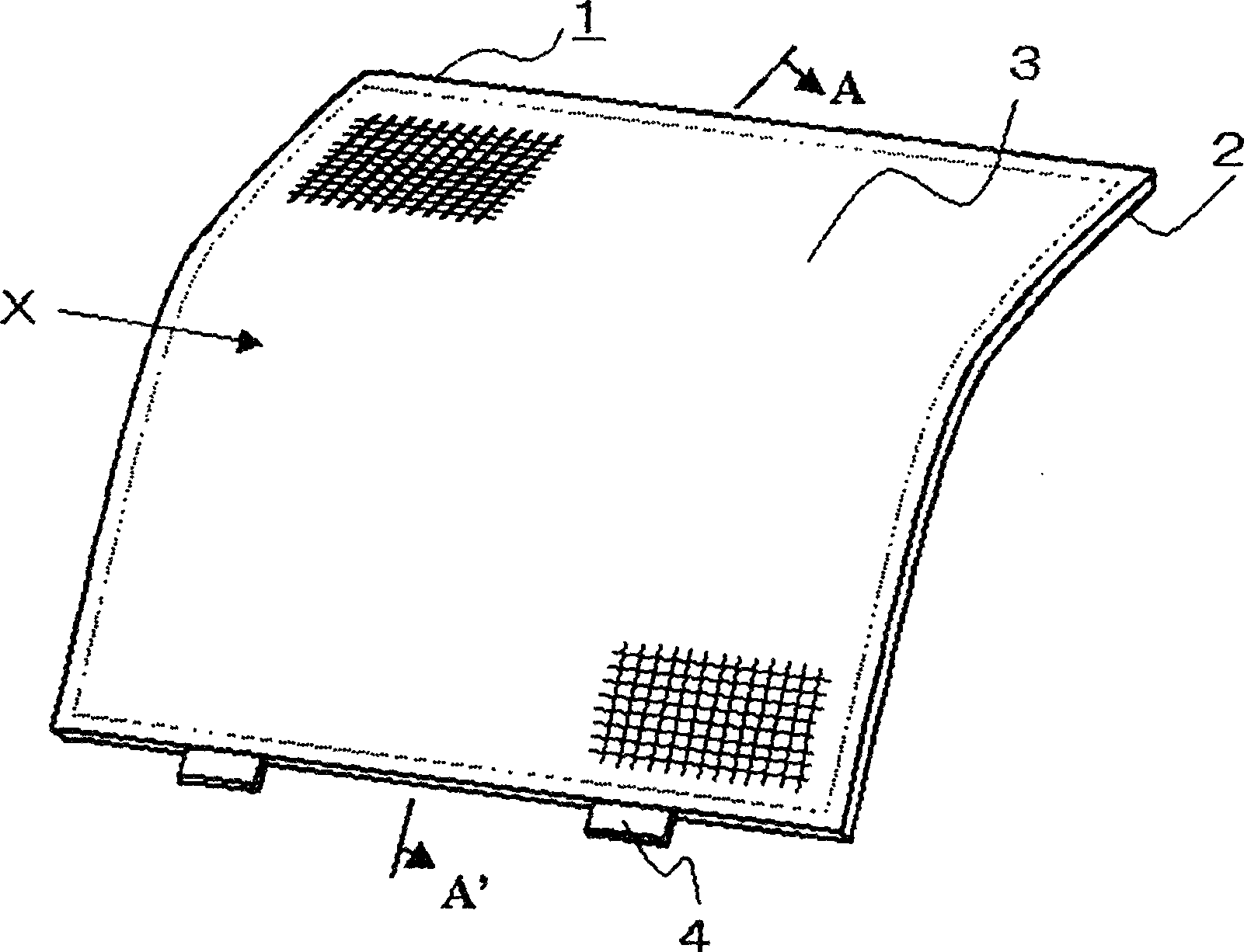
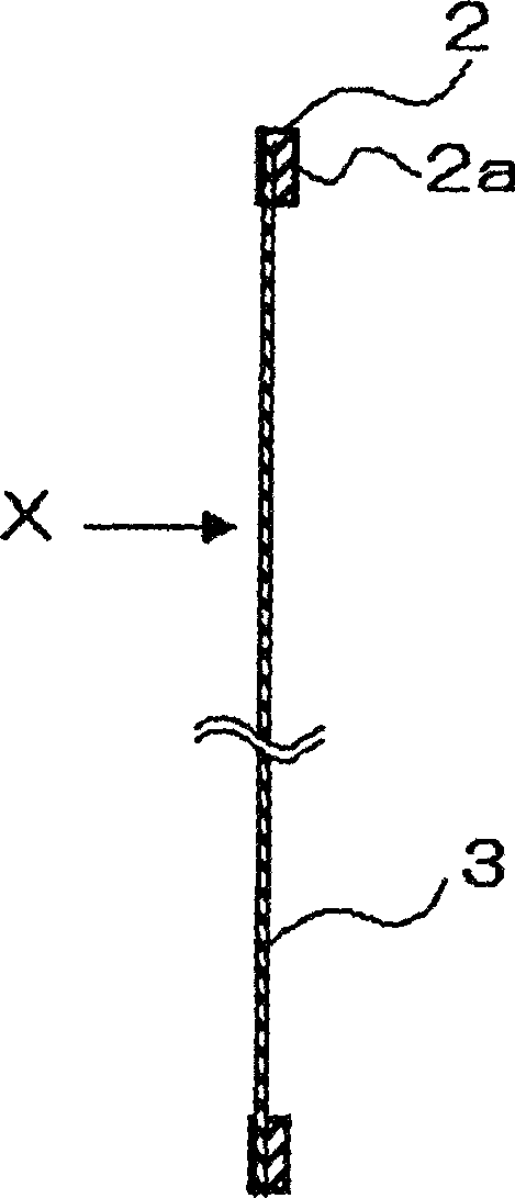
[0034] First, a first embodiment will be described using FIG. 1 . The air filter 1 is made of a flexible synthetic resin (such as polypropylene, etc.) through its outer frame 2, and fibers such as nylon or polyester, polyethylene terephthalate, etc. The net part (dust collecting part) 3 which is woven into a grid shape is welded on one side to be integrally formed. As shown in figure (b), the surface represented by X is the dust collection surface for dust filtration and adhesion, and the outer frame is formed on the opposite side surface, which constitutes the reinforced outer frame rib 2a. In order to show which side the front is, add paint on the front side to make a mark, and also can find a way on the shape of the insertion pin 4 of the frame of the air conditioner or the like.
[0035] By disposing such an air filter on the suction part of an air conditioner or an air cleaner, etc., during the removal of dust attached to the air filter, since there are no ribs on the du...
Embodiment approach 2
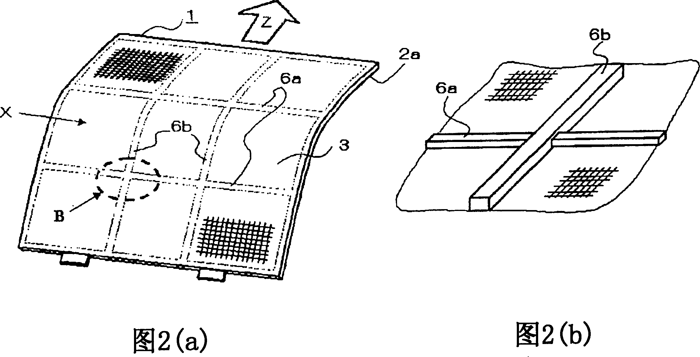
[0037] Next, a second embodiment will be described with reference to FIG. 2 . In the same figure, the difference from the first embodiment is that the ribs 6 for holding the reinforcing net portion are formed from the surface opposite to the dust collection surface X. By adopting additional ribs, the strength of the air filter as a whole is increased, and the dust collection surface is firmly held by each area. In addition, the reinforcing ribs 6 are formed to weld and hold the net portion, and since they are formed on the surface opposite to the dust collecting surface X together with the outer frame ribs 2a, the user can remove the dust stuck on the dust collecting surface X without being hindered by the reinforcing ribs. dust, and will not be hindered by the reinforcing ribs and retain dust as in the prior art.
[0038] As shown in Figure (b), when the air filter 1 is inserted in the direction indicated by Z with respect to the air blower frame, it is substantially at righ...
Embodiment approach 3
[0041]Next, a third embodiment will be described with reference to FIG. 3 . In the present embodiment, the outer frame ribs 2b are also formed on the dust collecting surface X side. In this way, it is possible to ensure that there is a certain height space between the dust attachment part and the touch surface. When the air filter is taken out from the air supply device, the dust attached to the dust collection surface will not be caught on the machine frame or fall inside the frame. . In addition, when cleaning with a cleaning machine, etc., even if the nozzle of the cleaning machine is cleaned outside the frame, dust will not fall due to the outer frame ribs 2b being caught to some extent.
[0042] In this case, it is necessary to form a metal mold on both sides. However, if the handle portion 5 of the air filter is formed at the same time, not only the user can easily take it out, but also can easily know which side is the front (or dust collection surface) .
PUM
 Abstract
Description
Claims
Application Information