Pipe joint

A technology for pipe joints and sleeves, which is applied in the field of pipe joints and can solve problems such as increased weight of pipe joints

Inactive Publication Date: 2005-12-14
SMC CORP
View PDF0 Cites 1 Cited by
  • Summary
  • Abstract
  • Description
  • Claims
  • Application Information

AI Technical Summary

Problems solved by technology

However, at this time, the weight of the entire pipe joint will increase, which is not advisable

Method used


Image

  • Pipe joint
  • Pipe joint
  • Pipe joint

Examples


Embodiment Construction

[0034] Next, illustrated embodiments of pipe joints in the present invention will be described with reference to the accompanying drawings 1-5.

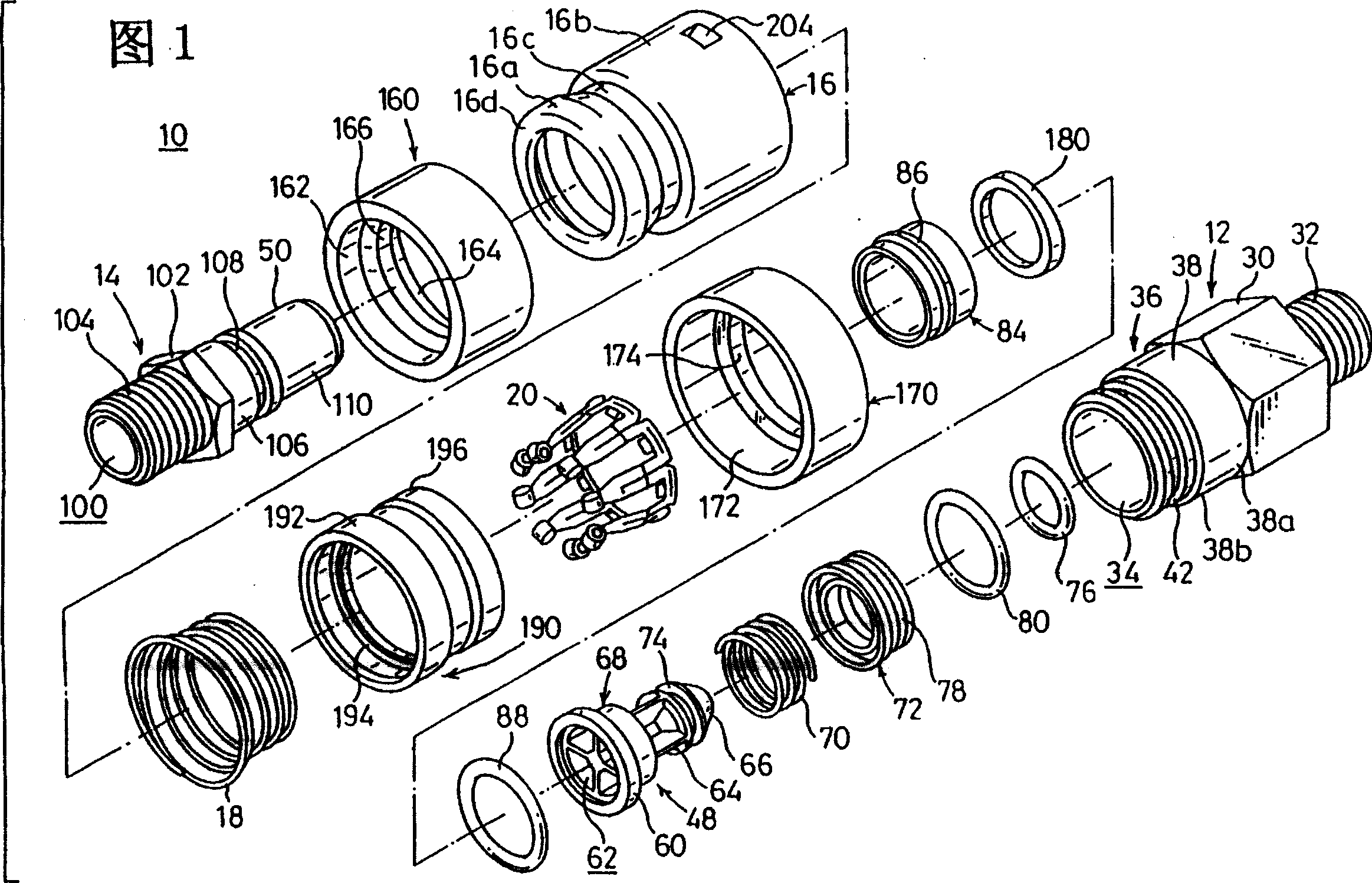
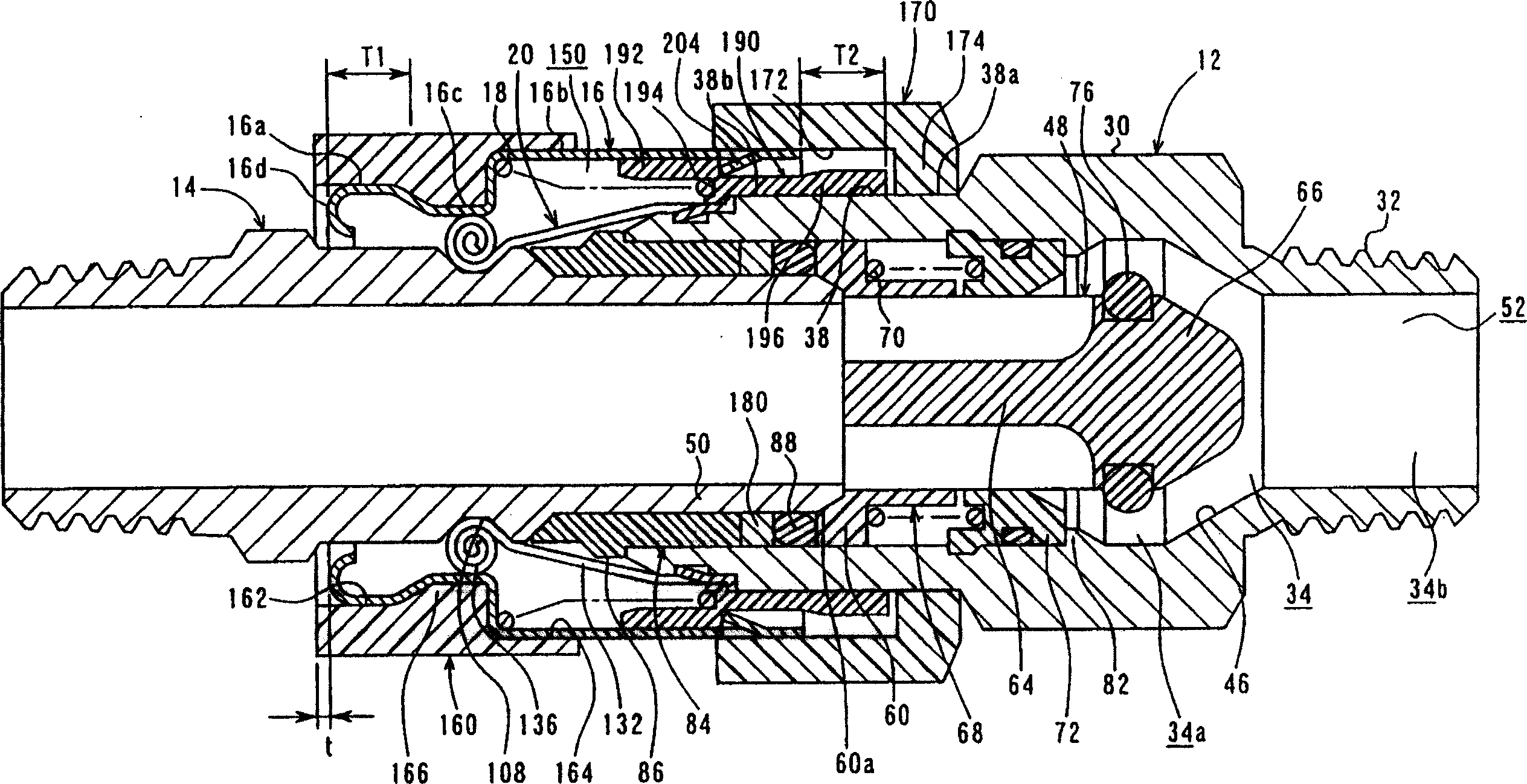
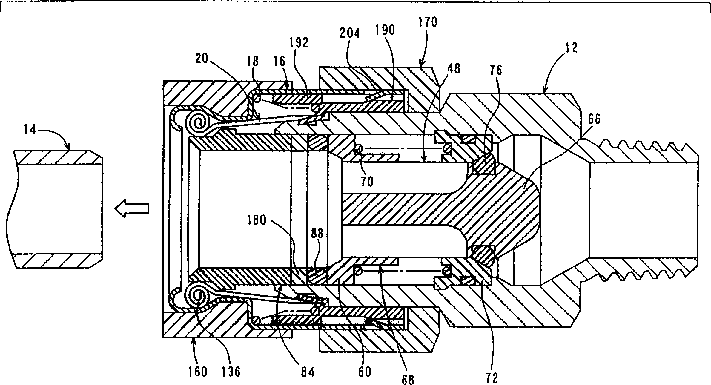
[0035] As shown in Figure 1, the pipe joint 10 in the embodiment of the present invention comprises: a first pipe joint part 12 made of metal; a second pipe joint part 14 made of metal, which is connected with the first pipe joint part 12 connections; a sleeve 16 made of metal is attached to the connecting portion of the first and second pipe joint parts 12, 14, and the sleeve connects and loosens the first and second pipe joint parts 12, 14, 14; a compression coil spring 18 to push the sleeve 16 in the direction of connecting the first and second pipe joint parts 12, 14 to each other; a faceplate 20 to cooperate the first and second pipe joint parts 12, 14 to each other ; a first protection part 160, which is installed on the front end of the sleeve 16; a second protection part 170, which is inserted into the front part of the first...


PUM


Abstract

A pipe joint comprises a first pipe joint part (12); a second pipe joint part (14), which is connected to the first pipe joint part (12); a set of pipe parts (16), which is attached to On the connecting part of the first and second pipe joint parts (12, 14), used to connect and loosen the first and second pipe joint parts (12, 14); an elastic part (18), The sleeve member (16) is pushed in a direction to connect the first and second pipe joint members (12, 14) to each other; and a protection member (160, 170) protects the sleeve member (16).

Description

technical field [0001] The invention relates to a pipe joint. In particular, the present invention relates to a pipe joint that protects the connecting portion of the pipe joint from external forces. Background technique [0002] Such as Figure 6 As shown, a conventional pipe joint generally includes: a tubular first pipe joint part 300; a tubular second pipe joint part 302, which is connected to the first pipe joint part; a sleeve 304, the Sleeve is attached on the connecting part of first and second pipe joint parts 300, 302, and its effect is to connect and loosen first and second pipe joint parts 300, 302; A compression coil spring 306, this compression coil spring pushing the sleeve 304 in a direction that interconnects the first and second fitting parts 300, 302; and a plurality of ball members 308 that function to engage the first and second fitting parts 300, 302 with each other . [0003] The first pipe joint part 300 comprises: a cylindrical part 312, the front...

Claims


Application Information

Patent Timeline
Patent Type & Authority Patents(China)
IPC IPC(8): F16L37/12F16L29/02F16L37/00F16L37/22F16L37/40
CPCF16L29/02F16L37/00
Inventor 内藤圭一郎
Owner SMC CORP
Why Eureka
Try Eureka