
Passive magnetic position sensor

A sensor and magnetic permeability technology, which is applied in converting sensor output, using electro/magnetic devices to transmit sensing components, instruments, etc., and can solve the problems of enlarged magnet, unclear output signal of sensor, and unavailability.

Inactive Publication Date: 2006-01-04
CONTINENTAL AUTOMOTIVE GMBH
View PDF1 Cites 0 Cited by
  • Summary
  • Abstract
  • Description
  • Claims
  • Application Information

AI Technical Summary

Problems solved by technology

In order for the position sensor to function reliably, the magnet must therefore not be infinitely larger, since this would cause many spring feet contacting the spring structure to be attracted simultaneously by the magnet, so that the output signal of the sensor would be ambiguous and therefore also will not be available

Method used


Image

  • Passive magnetic position sensor
  • Passive magnetic position sensor
  • Passive magnetic position sensor

Examples


Embodiment Construction

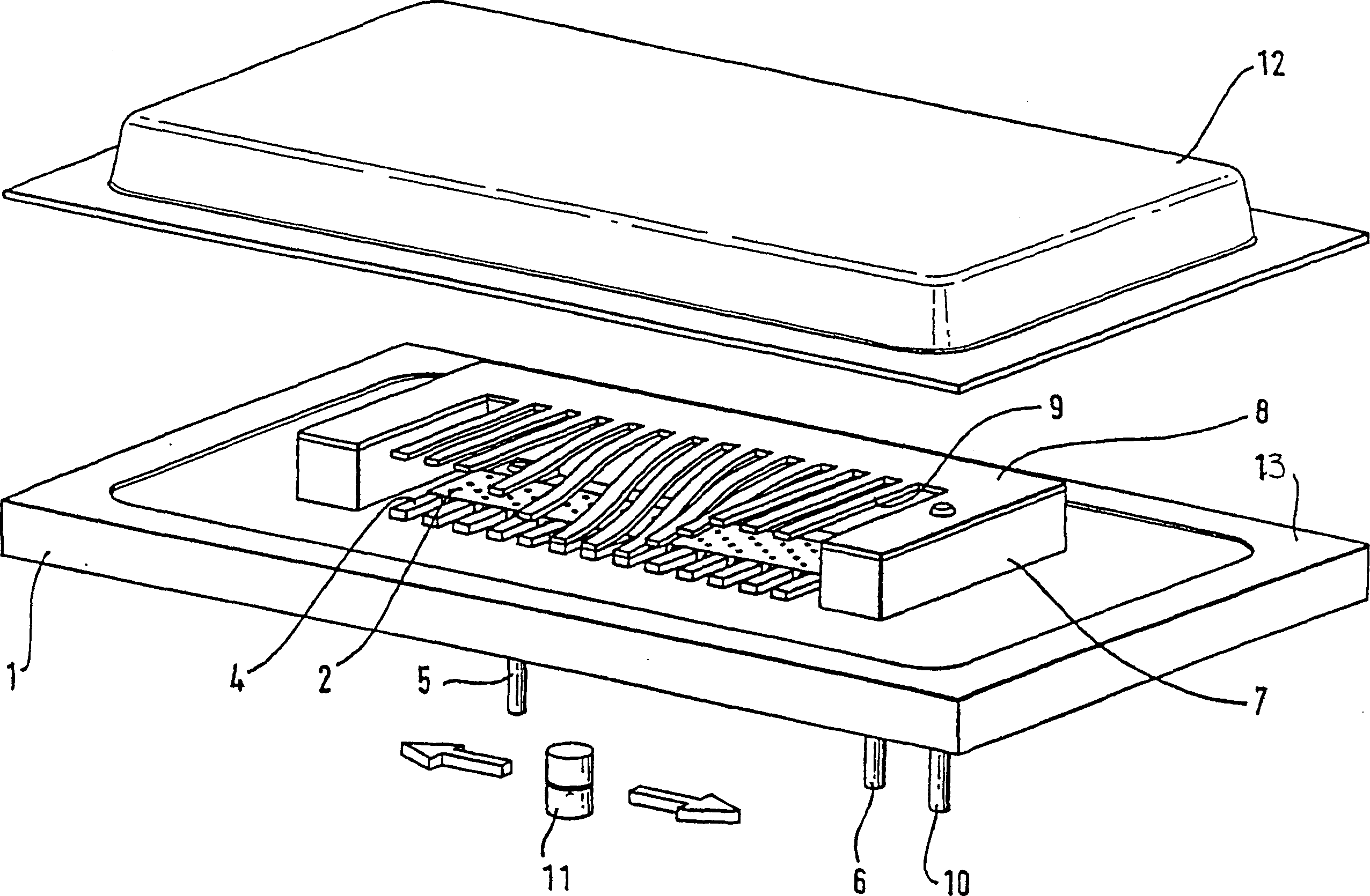
[0018] figure 1 A linear passive magnetic position sensor in the form of a potentiometer in a thick-layer arrangement is schematically shown. On the non-magnetic substrate 1 is a resistive network in the form of a layered resistive track 2 which is arranged between the electrical connection means 5 and 6 .

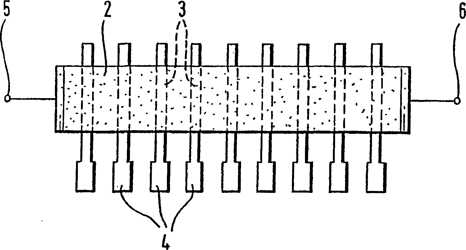
[0019] as by figure 2 It can be seen that a plurality of printed circuits 3 are arranged parallel to one another on the substrate below the resistive track 2 at a uniform distance. These printed circuits 3 are applied perpendicularly to the resistive lines 2 directly on the substrate 1 . The printed circuit 3 is partly covered by the resistive line 2 . The ends of each printed circuit 3 now form a contact surface 4 which is coated with gold or silver.

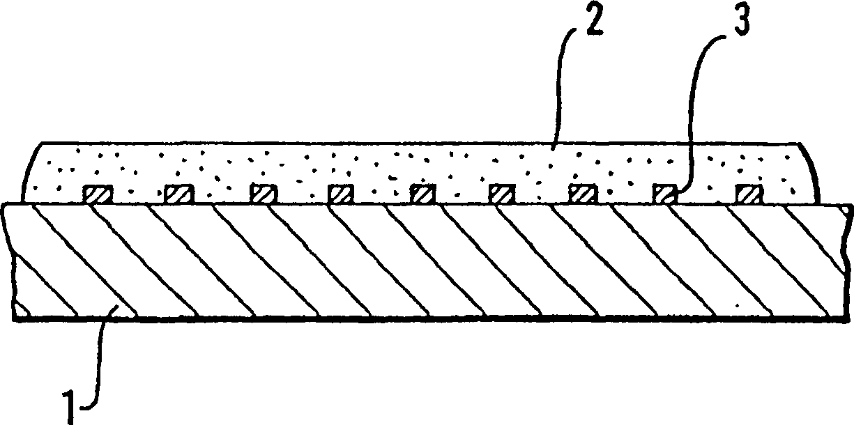
[0020] image 3 The sectional view shows that the printed circuit 3 is completely surrounded by the resistance line 2 in the area of ​​the resistance line 2 in order to ensure a reliable electrical connection. accord...


PUM


Abstract

The invention relates to a magnetic passive position sensor, comprising a substrate (1) with a resistance network (2) which is arranged on this substrate and is assigned a contact spring structure (8), which can be deflected under the action of a permanent magnet (11), with electrical connection between the resistance network (2) and the contact spring structure (8) being established by contact which is dependent on the position of the permanent magnet (11), the contact spring structure (8) and the resistance structure (2) being enclosed in a sealed housing (1, 12) and the permanent magnet (11) being movable outside the sealed housing (1, 12). In the case of a position sensor with improved magnetic force of the permanent magnet (11), the permanent magnet (11) is polarized in the direction of movement of the contact spring structure (8), a flux guiding device (14, 150; 156) for increasing the concentration of the force of attraction of the undisturbed magnetic field being arranged near the permanent magnet (11).

Description

technical field [0001] The invention relates to a passive magnetic position sensor comprising a substrate with a resistor network arranged on the substrate, the network being provided with a contact spring structure which is placed between permanent magnets It can be deflected under the action of the resistor network, wherein the electrical connection is achieved by contact between the resistor network and the contact spring structure, which depends on the position of the permanent magnet, wherein the contact spring structure and the resistor structure are enclosed in a sealed In the casing, and the permanent magnet can move outside the sealed casing. Background technique [0002] Such a position sensor is known from patent DE 196 48 539 . Both the resistor network and the contact structure are arranged on one substrate. A magnetic device is connected to a movable target whose position is to be determined, and the contact spring structure is deflected by this magnetic devi...

Claims


Application Information

Patent Timeline
IPC IPC(8): H01F7/02G01D5/165G01D5/251
CPCG01D5/2515G01D5/165G01D5/14
Inventor Z·彭扎K·埃克
Owner CONTINENTAL AUTOMOTIVE GMBH
Learn More